For this guide, I’m going to show how to construct a tube amplifier from a kit. Why a tube amplifier? Why not a transistor amplifier? Well, many people think the tube amps sound better than modern semiconductor-based amps. I’m not an audiophile so I can’t really tell although I do think it has a bit more of a warmer more nostalgic sound. The real reason is just to build something cool-looking, a throwback to the earlier days of electronics.
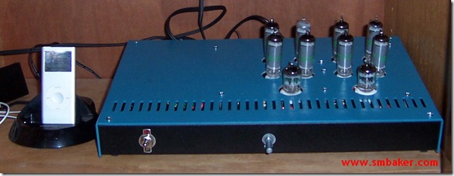
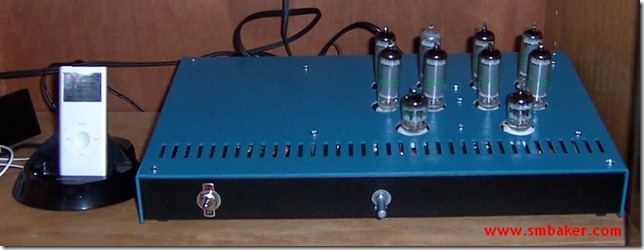
Let’s preview with a picture of the completed amp with a custom case sitting on display:
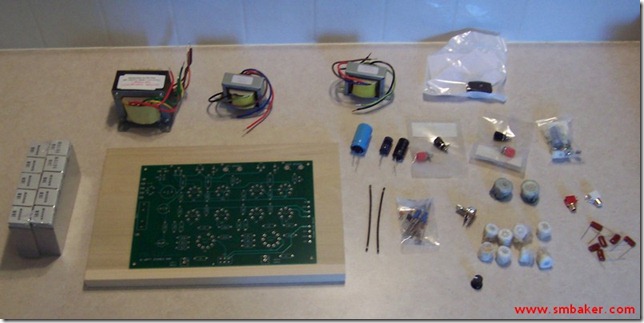
The kit that I will be building is the K-16LS made by S5 electronics. It’s a 16-watt amplifier with a total of 10 tubes. S5 offers a number of options including pre-amp and tone control, but I built the basic kit. Let’s get started by seeing what comes in the box:
On the left are the boxes of tubes. There’s a total of 10 of them. We’ll leave them boxed up until we’re ready for them. In the center is the main PCB, and a board that serves as a mounting platform (I’ll discuss mounting the amp in a custom case later). Above it is the power transformer and two output transformers. To the right we have the small parts including capacitors, resistors, some wire, tube sockets, and connectors.
Note that the kit does not include a case – that’s something that I added later. The kit is intended to be mounted to the wood board shown above.
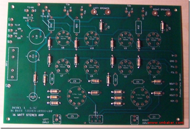
Before getting started, I recommend making a copy of the PCB layout. I did this by putting a piece of paper over the top of the PCB and rubbing a pencil on it. The reason for this is that if you wish to mount the amp in a case at a later date, you’ll want a nice template for drilling holes. You can safely ignore this step if you intend to mount the amp to the supplied chunk of wood …. but if you change your mind later, you’ll be sorry.
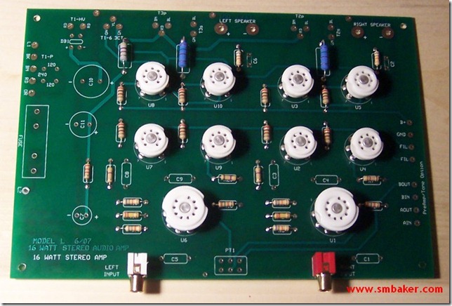
For our first step, lets solder all of the little half-watt resistors to the board:
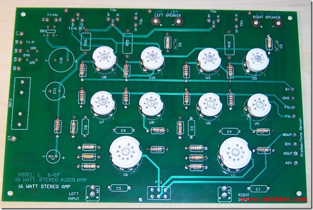
Next up are the tube sockets, all ten of them:
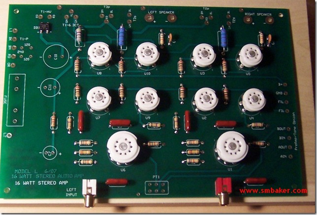
Now we add the RCA jacks for the inputs and a few of the bigger resistors:
Our next step is to add the bridge rectifier (a little 4-pin semiconductor) and the audio capacitors:
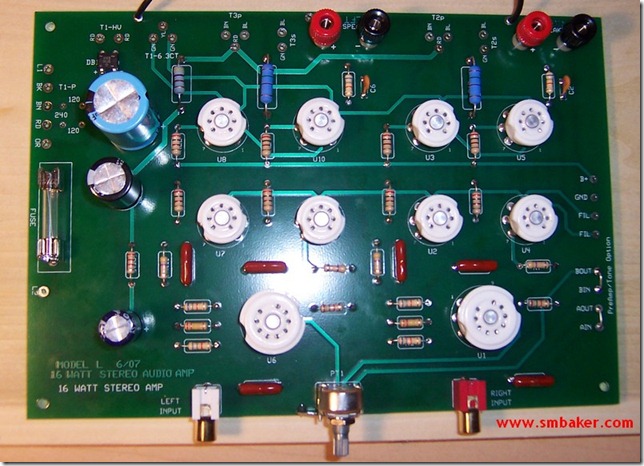
As our last step with the PCB work we add the remaining components. These include the large power capacitors, output speaker terminals, fuse, volume control, and a few jumpers. You should make a decision at this point as to how you intend to complete the kit. If you’re going to go ahead and mount it to the supplied board then mount the caps face up as I did. If you intend to mount the amplifier in some kind of case then you’ll likely want to mount the large electrolytic caps from the underside of the PCB so they won’t interfere with the case. For now I mounted them face up although I ended up having to change them later.
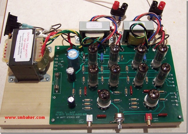
Our final step is to wire the transformers and install the tubes. The wires from the transformers are all soldered to pads along the rear of the PCB. Once you’re finished, mount the PCB and the transformers to the supplied board with the wood screws. Congratulations, your amplifier is completed and ready to go! (small note: I didn’t care for the included binding posts, and I was intending to move to a case anyhow, so as you can see I replaced the binding posts with some beefier ones. I also added a standard power connector and switch):
At this point your amp is ready to power up and go. For me, it worked great, sounded great, and worked the first time I tried it. The basic kit was very easy to build. Although it does require soldering, the components are all fairly large and easy to solder. It’s something that can be completed in an evening.
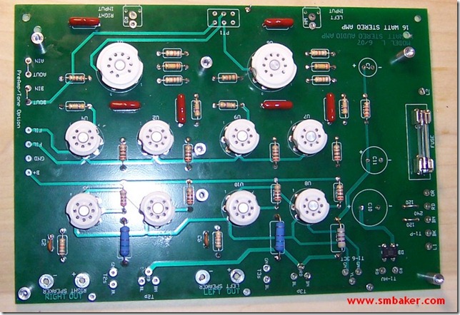
The next step was to place the amp in a nice case and show it off. For this I had to make a few revisions. I desoldered all of the wires from the board and removed the binding posts. The large power caps had to be flipped over and mounted up from the bottom. The volume control was removed so I could mount it to the case. I drilled some holes and mounted some standoffs so that the board could be screwed down from the top:
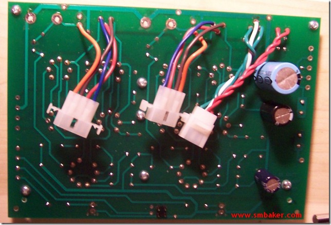
I also added molex connectors so that the transformers could be connected and disconnected without issue. Here is a view of the bottom-side of the board:
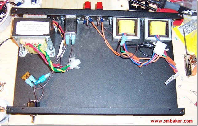
I believe the case came from Mouser electronics. It has a slight slant to the top which leaves just enough room in the back for the transformers. Finding a nice low-profile case that the amp would fit in was a bit of a chore. I really cut it close. In the case I installed the transformers, power switch, plug, binding posts, etc.
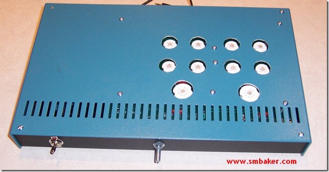
For the top of the case, I drilled holes using the template that I created way back at the beginning by tracing the PCB onto a piece of paper. The PCB was mounted using the standoffs and screwed down from the top. I used lots of standoffs when mounting the board as I didn’t want the board flexing or breaking when the tubes were pushed down from above.
Finally, Mount the tubes in the sockets and connect your favorite source. I used an old ipod connected to an old ipod dock accessory. Here is a picture of the completed amp on display:
