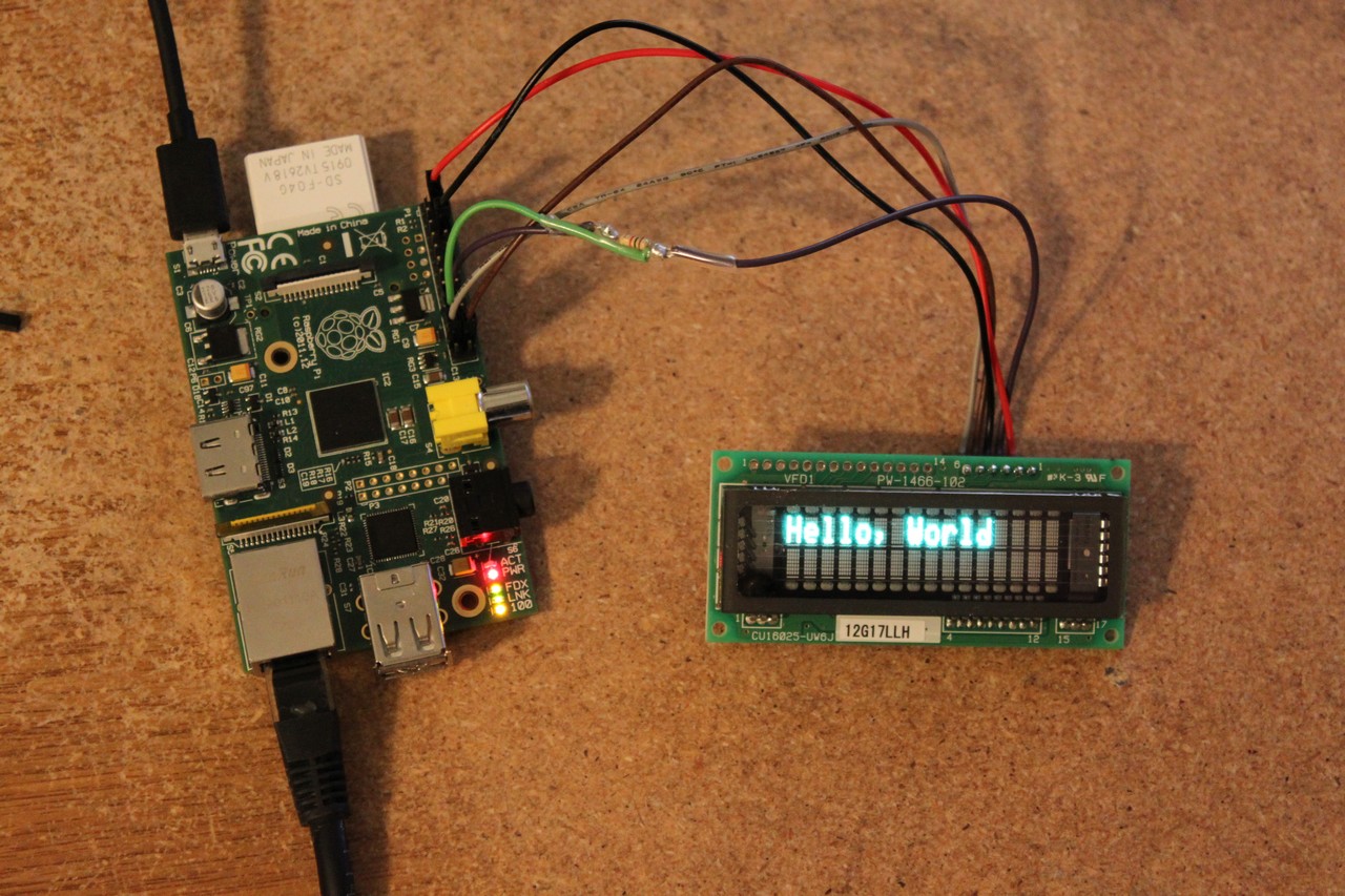
I’m in the process of building a home automation controller using my Raspberry Pi, and I figured it would be cool if it could display the current song and artist on my Pandora player. There were many options for a display — I could go with an LCD, an OLED, etc. I figured just to be different I would try a VFD display. VFD stands for “Vacuum Fluorescent Display”. VFDs are an older technology that has existed since the early 1960s. They differ from LCDs in that LCD displays typically have a backlight whereas a VFD emits light directly, in a similar manner to how a fluorescent light works. They often have a blue/green character color.
The first thing to do was to select an appropriate display. I settled on a Noritake CU16025-UW6J. This is a 2×16 character display that interfaces via SPI or Parallel. Using an SPI interface only consumes three or four of the pi’s pins depending on how you wire it. Minimizing GPIO use is always nice. I was able to pick up this display for $35 on ebay.
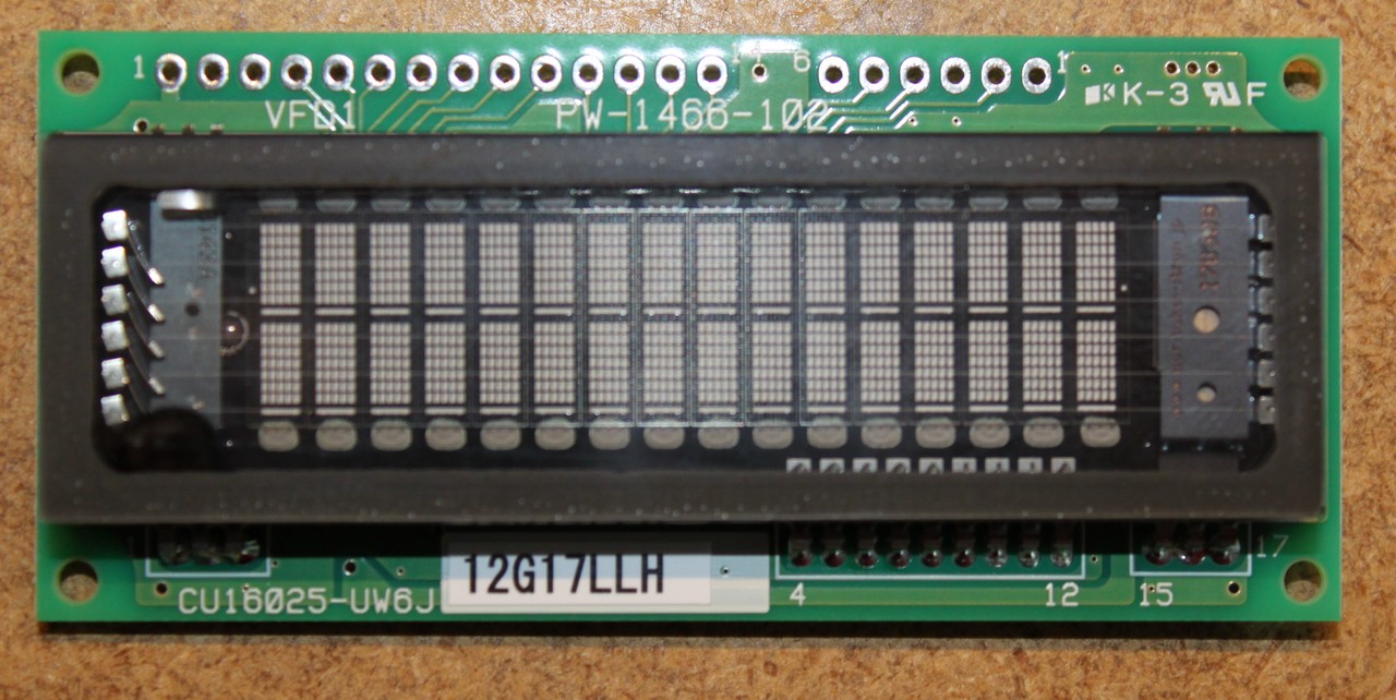
You’ll notice the display module has two headers. On the left there’s a 14-pin header (CN3) that’s used for parallel interfacing. On the right is a 6-pin header (CN1) that’s used for serial interfacing. We’ll be using the 6-pin header exclusively. On the back there is also a jumper, JP6, that you’ll need to populate in order to use the display in serial mode. Soldering JP6 was a little bit tricky as you have to solder it from the back of the board (I pushed the insulator on the header all the way to the top, soldered the header, and then pushed the insulator down).
Wiring
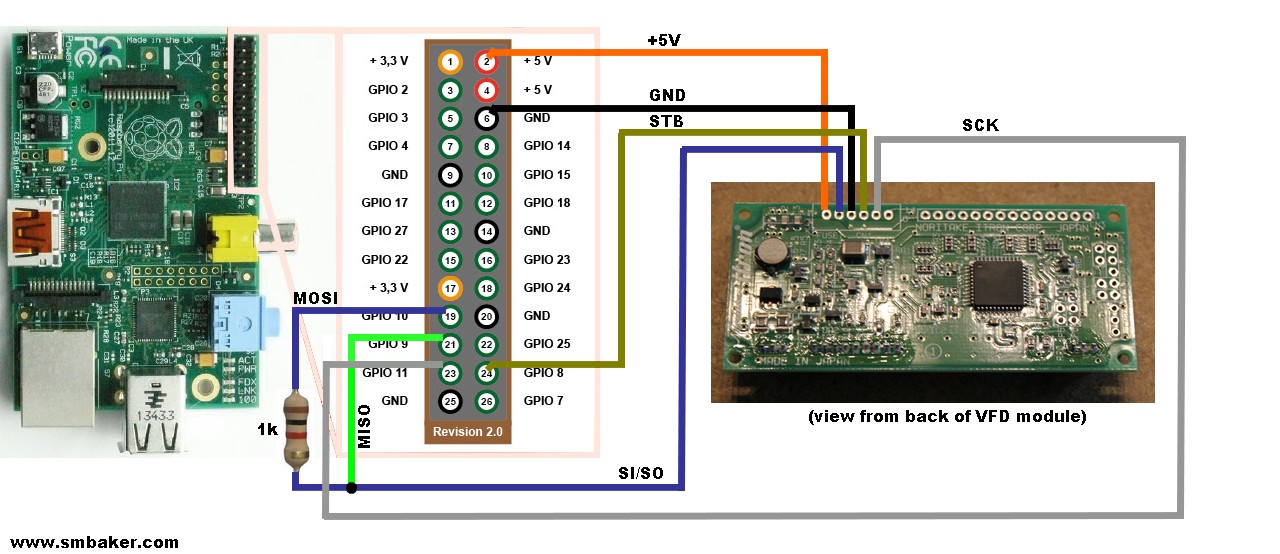
Let’s connect the module to our raspberry pi:
Click the diagram above to get a larger, more readable version. Note that we’re viewing the module from the back side, so pin 1 of CN1 is to the left and pin 6 is to the right. The VFD display requires two pins for power (+5V, GND) and three pins for IO (SI/SO, SCK, STB). The connections are:
| VFD Module> | Raspberry Pi | Notes |
|---|---|---|
| 1 | 2 | +5V |
| 2 | 19, 21 | SI/SO, use resistor on pi pin 19 |
| 3 | 6 | GND |
| 4 | 24 | STB / Chip enable |
| 5 | 23 | SCK |
Note the resistor inserted on the connection to Raspberry Pi ping #19 (MOSI). The reason for this is that we’re interfacing a 3-pin SPI device to a 4-pin SPI device. Pin #2 on the VFD is biderectional — sometimes it’s used to send data while other times it’s used to receive data. The Pi on the other hand has a dedicated send pin (19) and receive pin (21). If we ever entered a state, perhaps due to a programming error where the pi and the VFD were both outputting to the same pin with different values, a high amount of current could flow and the GPIO could become damaged. Thus the resistor.
I read several different web references on which resistor to use, with recommended values from 470 ohm to 10k ohm. I chose a 1K ohm resistor as that seemed sufficient to limit any current flow.
Setting up the Pi
Now we need to configure the pi to enable the SPI driver. Here’s a whole bunch of stuff to run:
# make sure the spi driver will be loaded

sudo emacs /etc/modprobe.d/raspi-blacklist.conf

(remove bcm2708-spi)

sudo reboot

# update our distro and install python development tools

sudo apt-get update
sudo apt-get -y install python-dev

# now let's build and install the python-spi library

mkdir python-spi

cd python-spi

wget https://raw.github.com/doceme/py-spidev/master/setup.py

wget https://raw.github.com/doceme/py-spidev/master/spidev_module.c

wget https://raw.github.com/doceme/py-spidev/master/README.md

wget https://raw.github.com/doceme/py-spidev/master/CHANGELOG.md

sudo python ./setup.py install
Note that this is for a somewhat dated Raspbian running on one of my old B models. For a newer raspian you might want to run raspi-config and use the advanced options to enable the SPI driver instead of editing /etc/modprobe.d/raspi-blacklist.conf.
Now we should have a raspberry pi with the SPI module being loaded automatically, and the python library installed.
Programming the module
I’m primarily a python programmer these days, so I put together a python module to operate the display. I cobbled the information together from a combination of the data sheet (http://qscomp.test.oxyonline.cz/out/media/GG72000101_CU16025-UW6J.pdf) and some C drivers floating around on the internet. I’ve checked the source into github at https://github.com/sbelectronics/pi-vfd. Here’s the module that I put together (note: check github for the most recent version; the code below will likely become outdated):
import spidev
import sys
import time

class VFD:
    def __init__(self, spi_num, spi_ce):
        self.spi = spidev.SpiDev()
        self.spi.open(spi_num, spi_ce)
        self.setDisplay(True, False, False)
        self.setDirection(True, False)

    def write(self, data, rs):
        if rs:
            self.spi.writebytes([0xFA, data])
        else:
            self.spi.writebytes([0xF8, data])
        time.sleep(0.00001)

    def writeCmd(self, c):
        self.write(c, False)

    def writeStr(self, s):
        for c in s:
            self.write(ord(c), True)

    def cls(self):
        self.writeCmd(0x01)
        time.sleep(0.005)

    def setPosition(self, x, y):
        self.writeCmd(0x80 | (0x40*y + x))
        time.sleep(0.005)

    def setDirection(self, leftToRight, autoScroll):
        cmd = 4
        if leftToRight:
            cmd = cmd | 2
        if autoScroll:
            cmd = cmd | 1

        self.writeCmd(cmd)

    def setDisplay(self, display, cursor, blink):
        cmd = 8
        if display:
            cmd = cmd | 4
        if cursor:
            cmd = cmd | 2
        if blink:
            cmd = cmd | 1

        self.writeCmd(cmd)

def usage():
   print "vfd.py  [args...]"
   print "     write "
   print "     goto  "
   print "     cls"
   sys.exit(-1)

def main():
   vfd = VFD(0,0)

   if len(sys.argv)<2:
       usage()

   cmd=sys.argv[1]
   if (cmd=="write"):
       if len(sys.argv)!=3:
           usage()
       vfd.writeStr(sys.argv[2])
   elif (cmd=="goto"):
       if len(sys.argv)!=4:
           usage()
       vfd.setPosition(int(sys.argv[2]), int(sys.argv[3]))
   elif (cmd=="cls"):
       vfd.cls()
   else:
       usage()

if __name__ == "__main__":
    main()
Let’s take a look at some of the more important bits. At the top of the file, there’s an import statement for the spidev module. That’s the module that knows how to talk on the SPI bus. Fortunately, we don’t have to bitbang the protocol; we can just call write() functions on the spidev module and the pi will handle the low level details of the protocol.
Next we see the initialization routine. the key bit of this code is the call to spi.open(), which include an spi device number and a spi chip enable number. For the connections we diagrammed above, both of these arguments are zero.
Each write to the display involves sending two bytes. The first byte is either 0xFA or 0xF8. 0xFA corresponds to the RS pin being high and 0xF8 corresponds to the RS pin being low. The RS pin is an artifact of the device’s parallel interface, but it’s important because this pin controls which functions are executed when we send the next byte. The datasheet has a table called “Software Commands” that explains which values of RS execute which functions.
For example, according to the datasheet writing the parallel interface with RS set to L with 0x01 sent causes the display to clear. So, for us serial interface users, that means send 0xF8 followed by 0x01. Similarly on the parallel interface to send the letter “A” to the display one would set RS to high and write 0x41. For us serial interface users that means send 0xFA followed by 0x41.
You can also read from the display, but I haven’t implemented that feature in my module, simply because the display doesn’t actually have anything that I care to read. The nice thing about not wanting to read anything is that you can lave the pi’s pin 21 disconnected if you like.
Using the demo program
In the video that you’ll see below, I typed these commands:
vfd.py cls
vfd.py write "Hello, World"
vfd.py goto 0 1
vfd.py write "Scott was Here"
There’s a whole lot more that the display can do that I haven’t shown in this article. For example, you can control the brightness. You can turn a cursor on or off. You can write 8 user definable characters to the device.


Hello,
I understand this is an old post, but I’m interested in getting a VFD display working with my Pi. I find these are great nostalgic displays ideal for home automation, server stats or anything else you want to cobble together.
I live in the UK with a little programming experiance and was wondering if you know of any good sources to get hold of one of these displays, or similar types. I understand these would be in short supply soon due to this type of technology.
Any help would be great appreciated.
Regards.
Hi Lee,
I purchased my displays from eBay.
Hi,
Wanted to resurrect this blog post really quick. I ran your provided code through python and just got instructions. When I try to do the commands that you mention at the end, it brings up errors. I’m very new to programming and the raspberry pi in general. How do I get this to work? What am I doing wrong? Any help is well appreciated! Thanks
For people searching for a new VFD module; these Noritake VFD’s are still stocked in the UK by Farnell and make a great display for headless Pi’s
I was wondering how would I go about running the script. I run the script in terminal using the python command “sudo python vfd.py”
and all it does is display this in terminal:
vfd.py [args…]
write
goto
cls
what the hell am i doing wrong doc?
Try this:
sudo python vfd.py write “Hello World”
Hi, Your code and tutorial are awsome!!
I have a different model which is working as expected but since it has 4 rows it is only using the first and third one. why is that?
thanks
Hi, I understand this is an old post, but I’ve just got myself this exact VFD display but unable to display anything. I’ve tried running sudo python vfd.py write “Hello World” but just returns the cursor. Any help would be much appreciated.
I’ve now managed to get this working, I’ve used the updated script on git that includes “self.spi.max_speed_hz = 500000”. I’m now just trying to figure out how to send commands to the display. I’m looking at digital clock project, or interface this with Kodi to display stats.
If you have any further suggestions or help, I would be much appreciated.
what needs to be changed in vfd.py to use it for Raspberry Pi Pico – RP2040 ARM Cortex M0 +
?