In this video, I build a Nixie Tube Frequency Counter. I’ve always wanted a Nixie Tube Frequency Counter, but never did find one on eBay that really jumped out at me… So I just decided to go ahead and build my own. My goals were:
- Nixie Tube Display
- Range from a few hundred Hertz to a couple of Gigahertz
- Sensitivity to 5oomV
- Six significant digits
Accuracy is something that I haven’t put a whole lot of thought into. I do have some TCXO (temperate compensated crystal oscillators) on hand, and some propeller boards on order to use them. Once I get the boards on hand, I’ll see if I can build up a version of the counter with verifiable accuracy.
The CPU
For a CPU I chose the Parallax Propeller. Many of my other projects have used the Raspberry Pi lately, but when it comes down to realtime programming, I like the prop. It’s easy to implement a deterministic realtime loop in one of the cogs while using the other cogs for other tasks, such as operating a display or user interface.
In building the prototype I first used a Parallax Propeller Professional Development Boar (PPDB), and then switched to a Propeller Proto-Board. There’s very little that needed to be done in the way of digital work — the counter signals basically come in on a couple of pins and the display data goes out via I2C to my nixie driver boards.
The Nixie Driver Boards
I used the same boards that I used for the Nixie Tube Calculator project, also described in an article and video of mine called ‘Controlling Nixie Tubes via I2C’. Basically the way these boards work is to use K155D Nixie Tube drivers controlled by I2C IO Expanders (MCP23017 and PCF8574). These boards can be daisy chained to control up to 32 Nixie Tubes. I only needed 8 tubes for this project, controlled from two of my Nixie Display modules. The modules also allow control of the decimal point, and there’s even a provision for LED backlighting.
The tubes I selected are the popular IN-12. They’re quite easy to obtain on eBay, cheap, and are easily socketed to a pcboard. Also available are the IN-15A and IN-15B which display a variety of symbols. The IN-15A allowed me to display “M” or “K” (for megahertz and kilohertz, respectively) and the IN-15B allowed me to display a “Hz”. Yes, I did waste tube budget on a tube that I only use to display the “Hz” symbol and nothing else.
Power Supply
I use a variant of my HVPSU, described elsewhere in my blog. It’s a TL494 boost converter that outputs around 160V to light the tubes. Also present on the power supply board is a 5V switchmode power supply to power the propeller proto board.
Lo-range front end
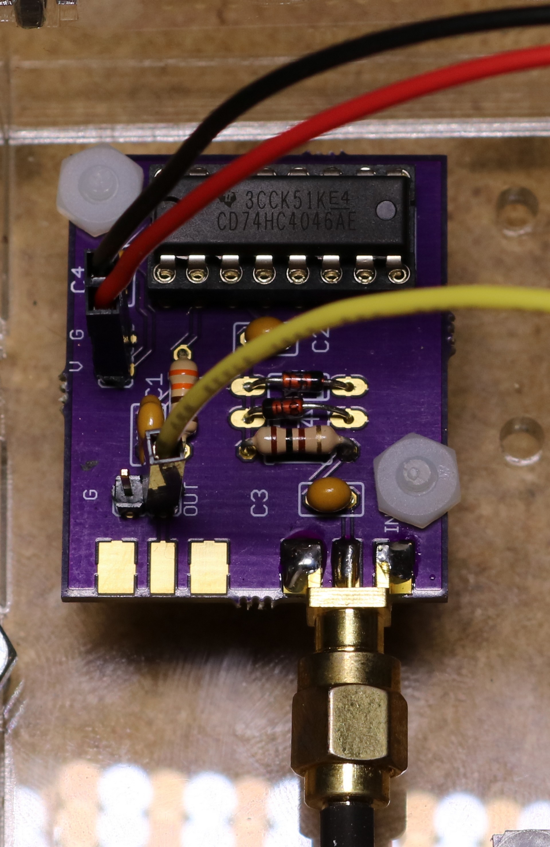
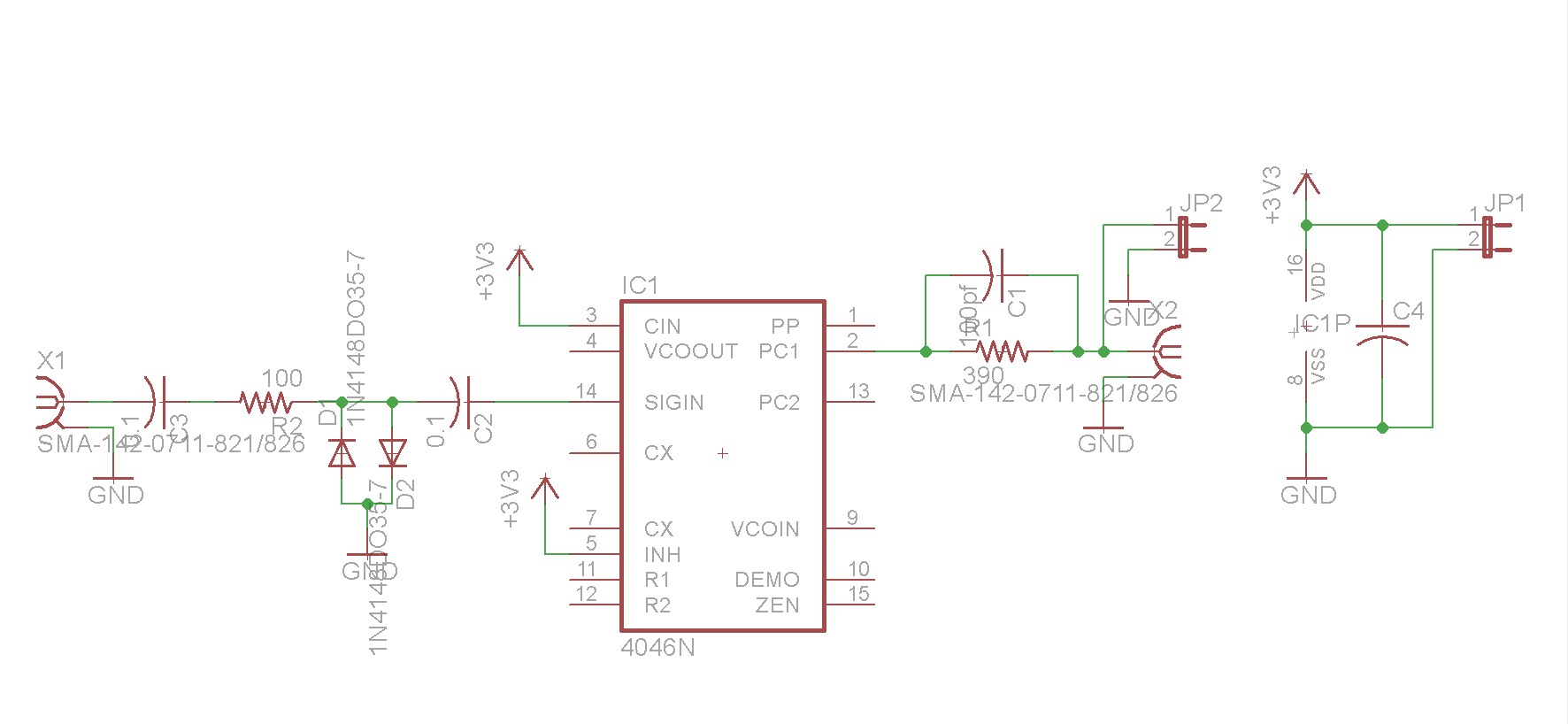
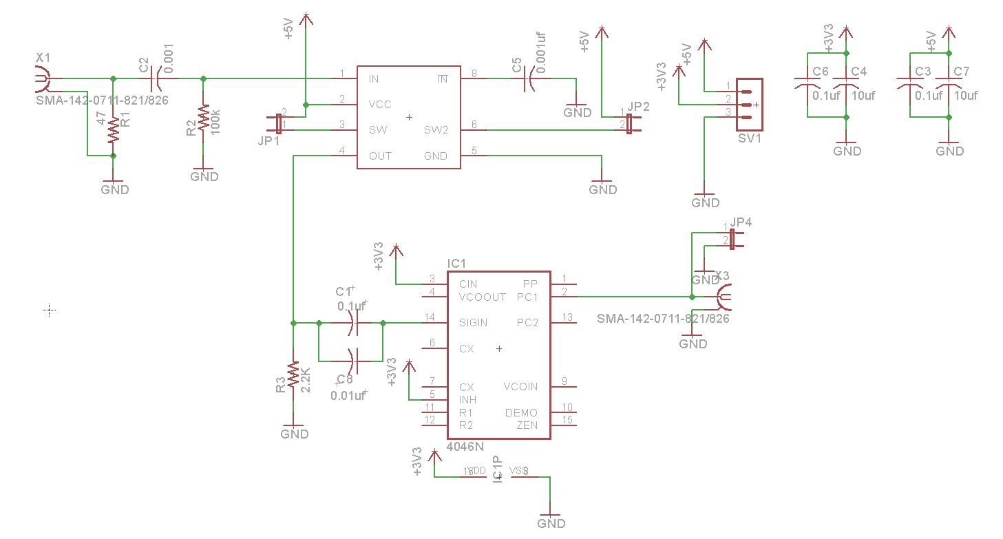
My first attempt to build a frequency counter had me connecting my function generator directly to the propeller. That worked fine for square waves, but failed miserably for sine waves. I quickly learned that I need some kind of a front end to condition and amplify the signal. Scouring the Internet for design ideas, I found the 74HC4046 chip. The 75HC4046 is a phase locked chip, but it has a nice signal amplifier built in. Here is a picture of the breakout board that I designed:
Schematic of the breakout board:
I was able to get the Propeller to count the output of the 74HC4046 directly to about 32 Mhz. We could probably get a bit more out of the 74HC4046 by adding a frequency divider and using the prop to count the divided frequency, but we’re not going to make it anywhere near our Gigahertz goal with that approach. So it’s time to develop a hi-range front end.
Hi-range front end
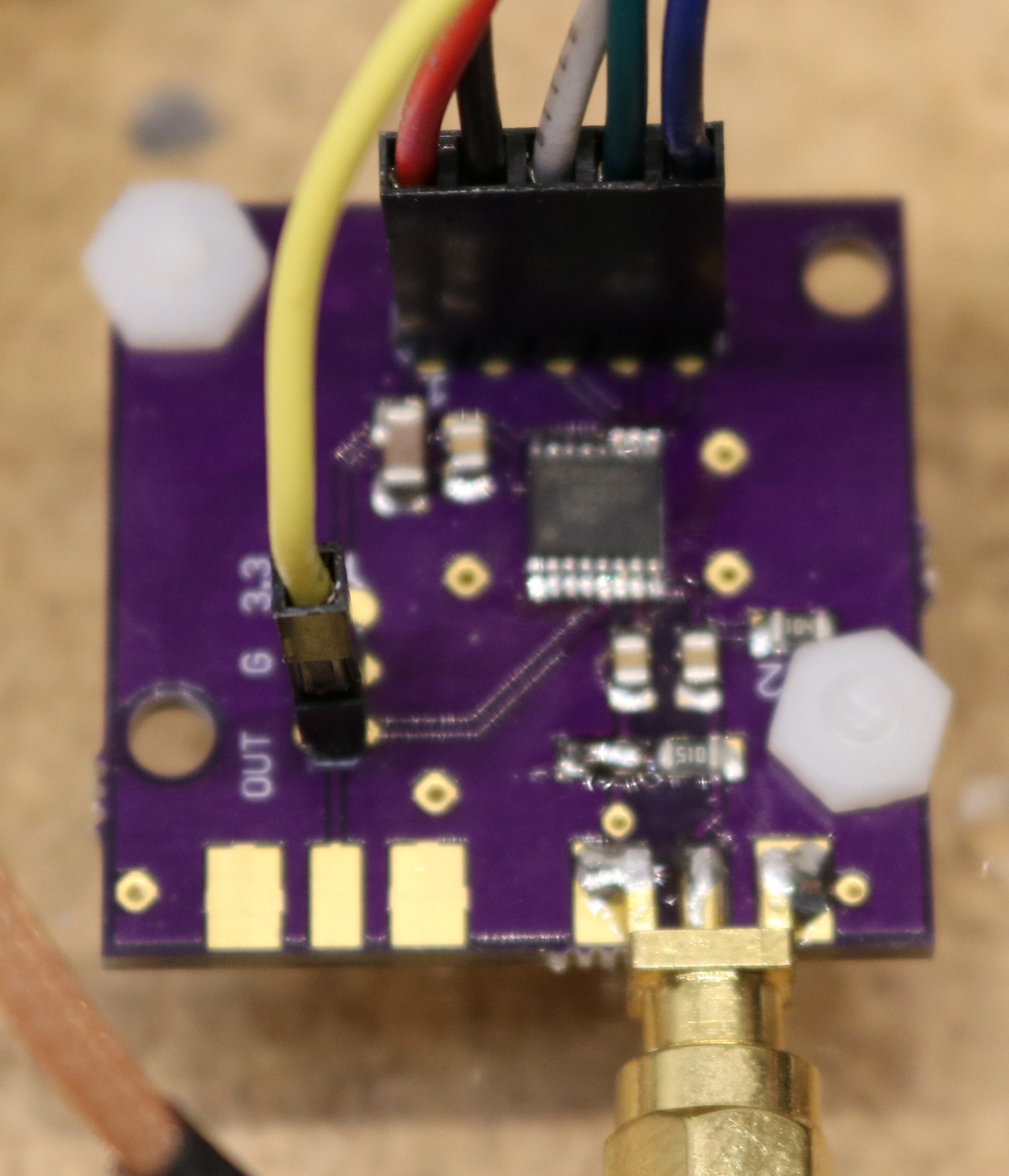
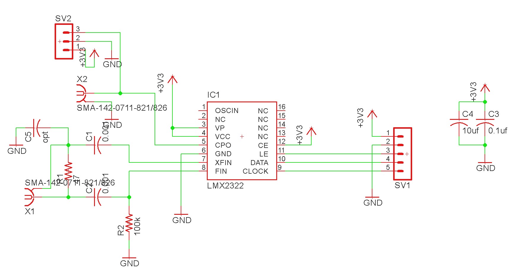
For the hi-range, I wanted to be able to get from 25 Mhz to a couple of Gigahertz. Again, scouring the Internet I saw some people using an LMX2322 prescaler in their designs. Like the 74HC4046, this thing is intended for phase locked loop applications, but we can get away with just using the detector and prescaler functions. It’s controlled via a serial interface that lets you configure the prescaler.
Configuring the prescaler is a bit weird, and took some time to figure out. It’s a 32/33 prescaler. It takes a pair of numbers, A and B, and it divides the input frequency by 33 A times, and then divides by 32 (B-A) times. It also has the restriction that B must be greater than or equal to 3.
So let’s take a simple example. Let A be 0 and B be 3. This is the minimum values that we can use. It’ll divide the input signal by 33 zero times, and then divide by 32 three times. This yields a divide-by-96 function. I ended up going with A=0, B=4, which yields a divide-by-128 function. Thus when there’s a 1 Ghz input signal, the LMX2322 will output 7,812,500 Hz. We just have to multiply our measured frequency by 128 to get our display value.
Schematic of the breakout board:
Initial Prototype
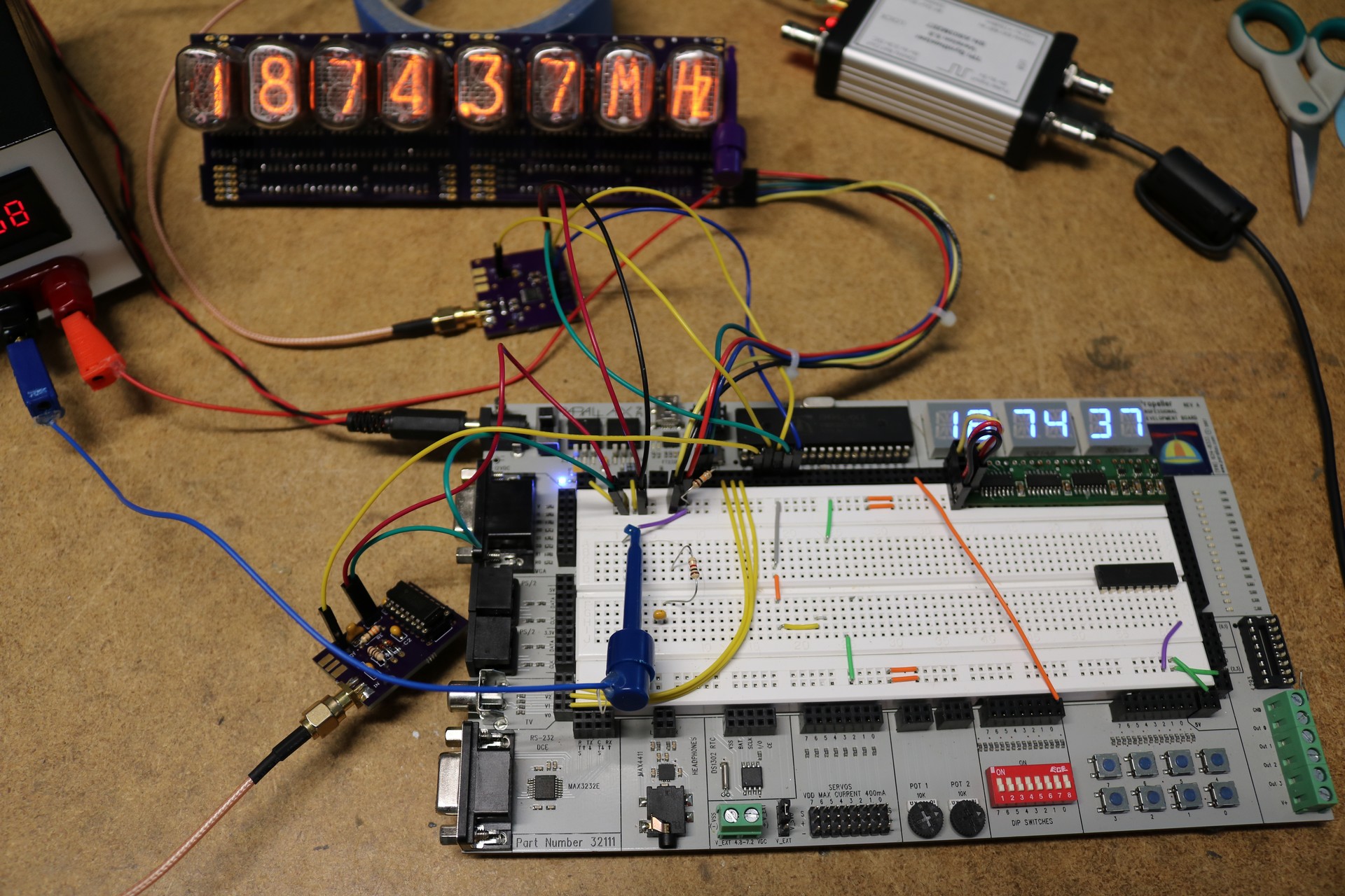
The initial prototype I constructed using a parallax professional development board:
Final Assembly
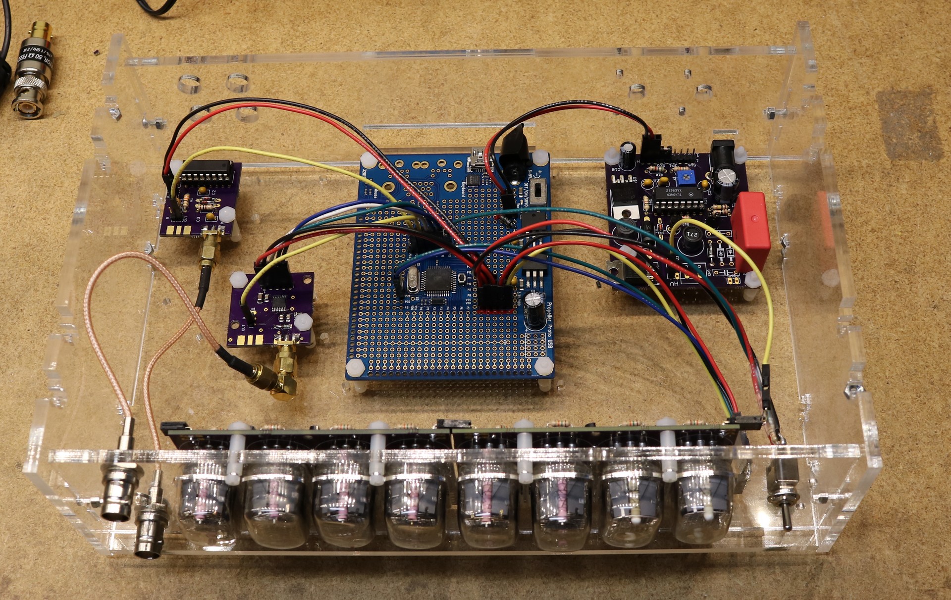
I designed a case, had it laser cut at Ponoko, and fitted the components to it:
Greater accuracy
The accuracy of a standard crystal isn’t really greater. There will be about a 50ppm manufacturing variation plus there will be variation of the overall oscillator circuit with temperature. To get a reliable frequency reference, it makes sense to use something called a Temperate Compensated Crystal Oscillator. You can get 5 Mhz TXCOs on ebay for about $15. Expensive, but it’ll get you an accuracy of 0.5ppm and compensation for temperature.
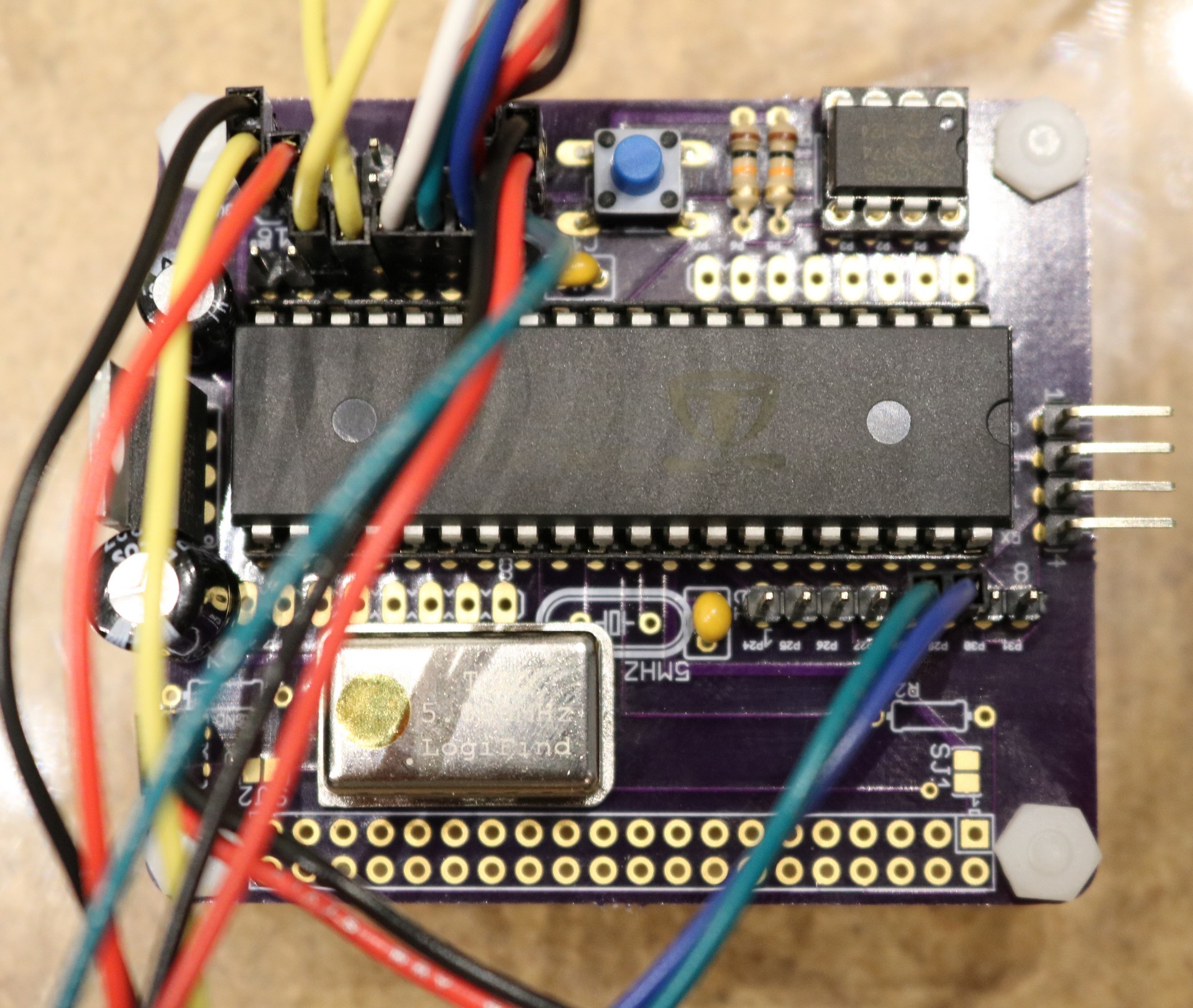
To use the TXCO with the propeller, remove the existing crystal and wire the TCXO’s output to the propellers XI input. The prop’s XO output remains disconnected. I made a custom PCB that mounts a 40-pin propeller, eeprom, TCXO, and voltage regulator. The board replaces the propeller proto-board in the above pictures. Here is an image of the new board. The TCXO is the big metal can:
Alternative Hi-Frequency Front End
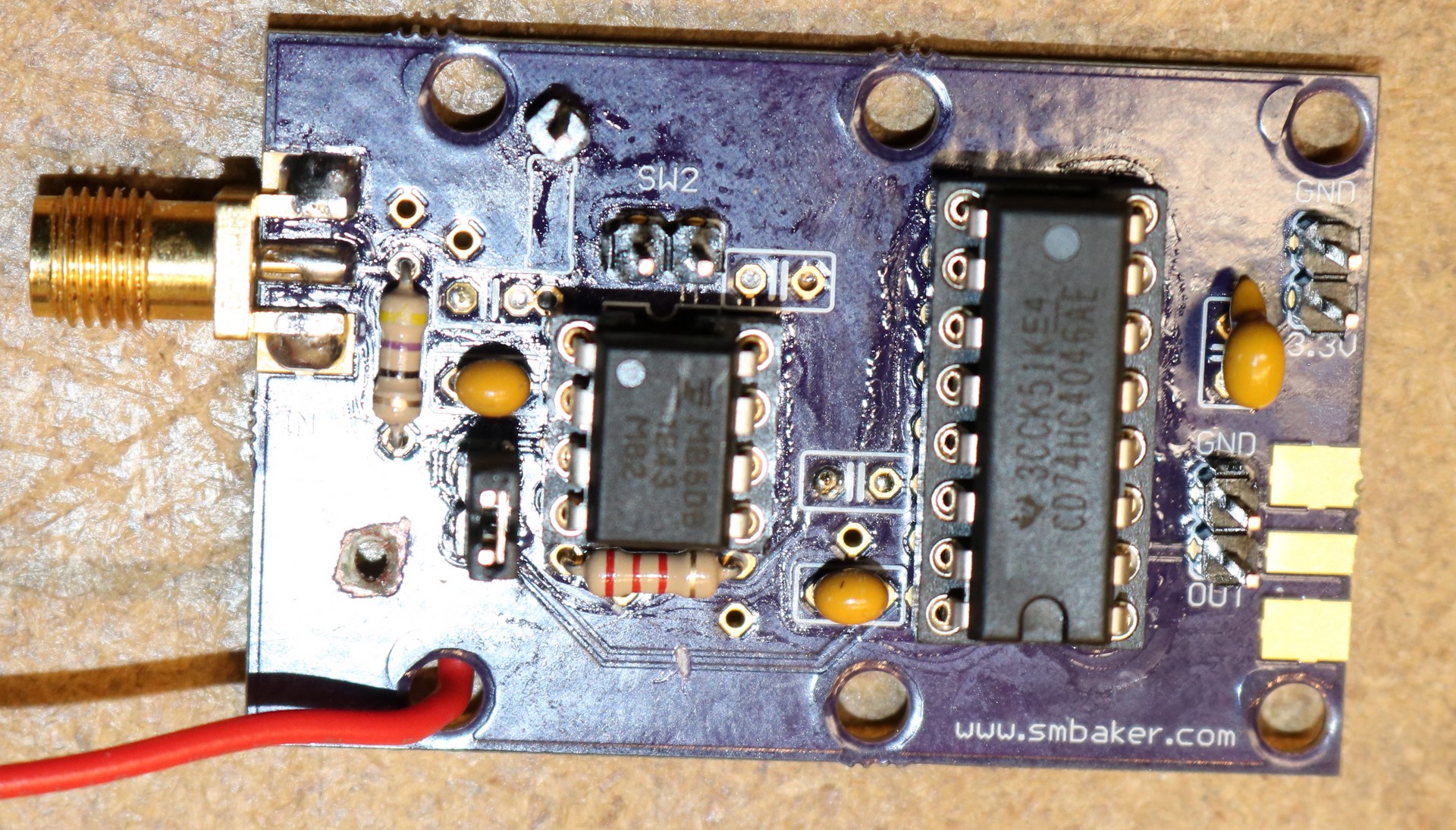
There were two problems with the LMX2322 as implemented in the project: 1) it topped out somewhere around 1.9 Ghz, and 2) Sometimes it wouldn’t get setup properly over the serial connection to the propeller. I decided to move to a different hi-frequency frontend, the MB506. The MB506 can be configured to divide by 64, 128, or 256. This eliminates to dink around with any serial communication between the prop and the chip. It also seems to function reliably up to about 2.44 Ghz. The problem with the MB506 is that it doesn’t output a nice IO-compatible square wave like the LMX2322 did. It outputs an annoying 1.6 Vpp, centered on ground. I tried a few tricks like using pullup resistors and transistor drivers, but ultimately I decided the safest bet was to just feed it into a second 74HC4046. The resulting schematic is shown below:
The new PCB is below:
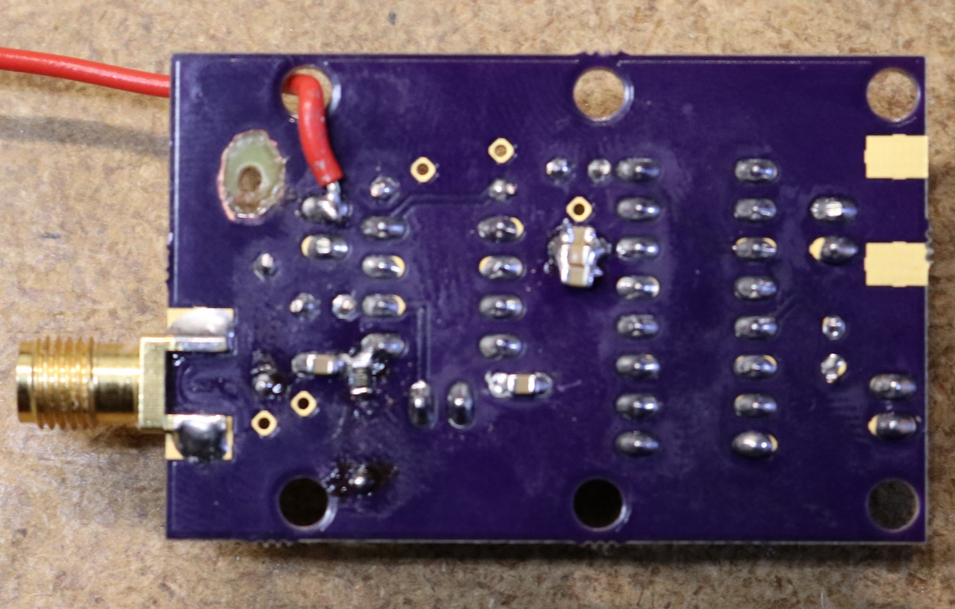
As you can see there’s a weird red pigtail going to the underside of the board. That’s because I failed to properly read the datasheet the first time and didn’t note that the MB506 was a 5V device instead of a 3.3V device. To be fair, it worked pretty well at 3.3V. There was some instability with the SW1/SW2 jumpers at low frequencies. However, it works much much better at 5V. You can also see that I designed this board as a through-hole board. I had some issues with frequency response as we got up around 2.4 Ghz. So I pulled the key through-hole components and soldered SMD in place from the underside of the board:
I’m still planning on giving it one more shot with through-hole components once I get some new caps in (lead length can be really critical in RF designs, and I need to get the right size caps to fit the through-hole patterns instead of trying to fudge the wrong size packages into place). If I can’t make the through hold design, then I’ll switch over to SMD. One board board revision should do it.
The good news is that the above board was stable to around 2.9 Ghz, which is beyond the spec of the MB506 chip.
Source Code
The source code is available on my github repository at https://github.com/sbelectronics/prop-freqcnt
Hi Dr Backer
I like this project, I wanted to built something like this but in small scale 6 digits measuring 30Mhz max. but i wished that you explain more about the CPU counter board, thats is the main thing to built this counter.
Please, can you provide the connections diagram of the controller how wires connected to right pins ?
As you mentioned there’s another one of your videos concern the nixie tubes board, I looked at it but found nothing I can get to know how to built one, still need the diagram of tubes with drivers including the I2C, can you provide that too ?
Thanks
At the end of the video, it shows the frequency reading demonstration, it looks like the readout response when injecting the signal from the generator is slow, at the moment when you were turning the generator knob the readout wasn’t following the same speed as the knob, the counter might have the gate timing issue, not quiet enough time to read faster !!