In this blog post, I design a single step module for the RC2014.
[TODO: Insert Video Here]
If you haven’t read my introduction to retrocomputing yet, then please start there, as it describes the Z80 platform that I’m using.
The single step module is an alternative to the bus supervisor that I designed in the previous blog post. The bus supervisor implemented a slow clock, but it required a raspberry pi to do so. I wanted to design a module that required no raspberry pi, and added the ability to single-step and to auto-step the CPU. So why single step? Single-stepping is another feature that is handy for assembly language debugging. It allows you to execute exactly one instruction at a time. For each instruction, the CPU will wait for the user to press a button.
Auto-stepping is the other feature that this board implements. Rather than require the user to push the button, we can use a 555 timer to “push the button” for us. This makes the program run slowly, for example at a rate of 10 instructions per second or 100 instructions per second.
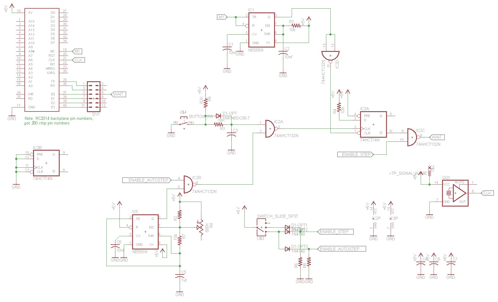
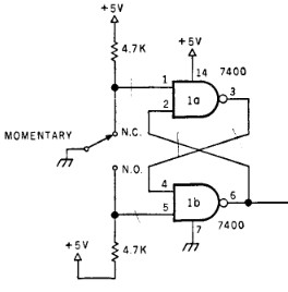
As the basis for my single stepper, I used this post at the Z80 Computer Project blog. It starts off with a circuit designed by Steve Ciarcia and published in his book Build Your Own Z80 Computer, which is available online. Ciarcia’s design uses a flip-flop to implement the single stepping. The M1 signal is fed into a one-shot and used as the clear signal for a 7474 flip-flop. The M1 signal clears the flip-flop, which sets the Z80 wait line low. This will cause the Z80 to wait until the wait line is set high again. A debounced pushbutton is used to clock a “1” into the flip-flop, which will in turn raise the wait line and unblock the CPU. The next M1 cycle will clear the flip-flop and re-enter the wait state.
The Z80 Computer Project blog post replaced the monostable multivibrator used in Ciarcia’s circuit with a 555 timer. My modification replaces the SPDT step switch with a SPST pushbutton:
One thing to note — both the Ciarcia book and Z80 Computer Project Blog showed the Pre input (pin 4) of the 7474 flip-flop unconnected. This caused chaos in my implementation. Sometimes it would work fine, other times the flip-flop would pick up noise and the wait pin would oscillate. I terminated pin 4 to 5V and the chaos went away.
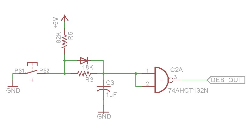
The idea for the switch debounce came from The Ganssle Group’s blog post on switch debouncing. So what is switch debouncing? When you flip a switch or push a button, it doesn’t simply change from one state to the other, there’s a noisy phase where the state flips back and forth a few times as the metal is just starting to touch. This will glitch your typical DC logic circuit. So we need some circuit to filter out the noise and get us only the state change event from the switch.
Ciarcia’s circuit used an SPDT switch and a couple NAND gates SPDT buttons aren’t super easy to find, and I wanted to use a SPST button. So I tried the RC schmitt trigger switch debounce circuit shown in the above schematic. The RC uses a network turns the noisy switch closure into a slower capacitor discharge, and the switch opening into a capacitor charge. Since it takes time to charge or discharge the capacitor, we eliminate the noisy spikes.
Note that the diode in the above schematic is optional, and is not necessary given the resistance values used above. The ganssle blog post gives the appropriate math.
The first time I built the circuit, I made the mistake of connecting the RC network to a plain ordinary 74HCT00 NAND gate. It’s important that you use a Schmitt trigger NAND gate,74AHCT132N. The Schmitt trigger includes hysteresis, which is necessary to prevent false triggering on the switch debounce. You can read more about Schmitt triggers on wikipedia.
The other change I made to the circuit is adding the autostepping feature. This is a second 555 timer configured as an oscillator. A NAND gate is used to enable or disable the output of the 555, and another NAND gate is used to combine the 555’s output with the pushbutton. Basically what happens is the 555 timer pushes the button for us. The values given in the schematic allow you to adjust the frequency from just under 1 Hz to around 100 Hz. It’ll depend on the specific capacitor you have as capacitors often have a fair amount of tolerance.
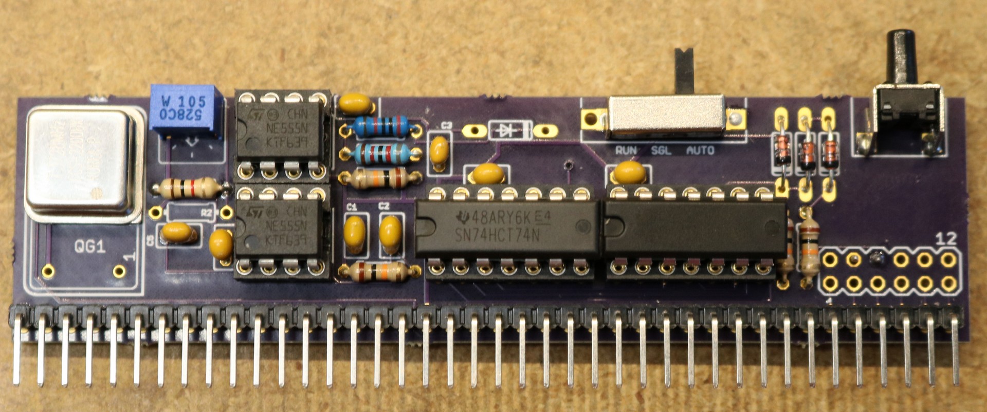
There’s a selector switch that lets you select “Run”, “Single”, or “Auto” modes.
Also on board is an optional 7.3728 Mhz oscillator. This allows the single step board to replace the RC2014’s clock board, saving a slot in the backplane.
Here is a picture of the completed single stepper module:
PC-Board ordering
As with my other boards, I’ve made it available on Osh Park. Please note that there was a revision to the board that has changed the routing from the version that I demonstrated in the video. It was a one pin change to supply 5V to PRE input of the flip-flop (this is consistent with the schematic above). I have not tested this specific revision of the board, though I have every expectation that it will work. Nevertheless, there is some risk associated with an untested layout.


Hi Scott
Are you able to sell any of your RC2014 boards? I have no idea how to produce a PCB circuit board from the circuit diagram.
I too have an RC2014 computer and would like to expend it. I like in the UK.
Regards
David
I’m slowly making them available on Osh Park. I don’t actually make any money on it, and Osh Park will sell you three boards when you only need one, but it’s a way to get them produced.
Currently the RTC board is available. I’ll probably put the Bus Monitor board up next. The Bus Supervisor and Slow Stepper both required modifications, so I have to upload a new board design to Osh Park before I can make them available.
Mr. Scott, If you’re like me, you have several projects going at once, and are always spread pretty thin. I have an RC2014 going, with boards of my own in progress. I am very attracted to your Bus Monitor, and ordered a 3-set of PCBs (still waiting); thank you for sharing that design! Now I’m hoping you can finish and release the Single-Stepper so I can order them too. I figure you need to hear from us, or you’ll move on to something else! Thanks again for all the publishing.
–Tony Drake in Maryland
Thanks for the interest, Tony. I’ll see about getting the Single-Stepper available on Osh Park soon. I think the issue was that I had a board revision that I made, but I haven’t yet vetted the changes.
Scott
Single-stepper link is live now in the blog post.
Scott
Mr. Scott, Thanks for getting your single-stepper board design on OSH Park! I immediately placed my order after I saw your blog post. Running the Bus Monitor and Single-stepper together is going to help debugging tremendously, and the whole RC2014 setup is going to look fabulous. Muchas gracias!
–Tony Drake in Maryland
Hi Scott,
Do you happen to remember where you found the oscillator? I’m hitting a wall trying to find the dip14 ones rather than a straight crystal. Thanks!
Sure, the 7.3728 Mhz oscillator was digikey part number XC1181-ND.
Hi Scott,
Do you have the part numbers of both the selector switch that lets you select “Run”, “Single”, or “Auto” modes and the single step push button?
Your boards have greatly enhanced the RC2014!
Regards,
Chris
I bought them on eBay. Try searching for “10Pcs 4Pin PCB 3 Position On/On/On 1P3T Miniature Slide Switch Right Angle” and “25 Pcs 6x6x10mm PCB Mount Momentary 2Pin Right Angle Push Button Tactile Switch”.
That’s brilliant, many thanks Scott.
Hi, Scott-san
I’m very interested with your project also this time.
I made similar PCB reffering your project.
First of all, I checked my parts box and prepare the parts for this stepper.
e.g. I don’t have HCT132 so I apllied HCT00 flip flop circuit and alternate switch.
I have amended STEP EXECUTOR PCB based on this project at easyEDA and ordered JLCPCBs same as before.
Now I’m waiting the parcel, and preparing for soldering parts.
Thanks again! Your blog posts are very informative.
I’m really getting stoked with retro computing life!
Regards,
The single step is nice. But, I am interested in taking it to the next level. Probably take some “smart” logic.
For each Machine cycle, I want to output over a serial bus: Address; OpCodes; all Regs (If Possible) & flags.
This would first be built on a TS2068 Bus…
But, could be useful on the RC2014…
Is this doable? Thoughts?
Hi,
Would HC132 or LS 132 work properly instead of 74AHCT132N?
Thanks