In this video, I turn an 80/24A multibus single board computer into a Series II development system running the ISIS-II operating system
Why?
I’ve had a fascination with ISIS-II and Multibus ever since a year or so back when I got my hands on an iPDS Personal Development System. While the iPDS itself is not multibus, it does share several traits, such as the use of multimodule sockets for expansion and the ISIS-II operating system. ISIS-II was a fun OS to play with, and I spent some time making speech synthesis and music multimodules and writing software to use them on the iPDS. However, the expandability of the iPDS is somewhat limited, and it’s cumbersome to pull boards in and out of the iPDS when experimenting.
I sought out a platform that would give me more versatility and expandability while still letting me run either ISIS-II or CP/M. That platform the is the MDS-80 series of development computers, and those computers used Multibus.
Choosing a multibus CPU board
I started with Joe’s On-line Multibus Circuit Board Guide which is a fairly comprehensive, but not 100% complete list of multibus (SBC) and multimodule (SBX) boards. I knew that I wanted an 8080 platform, not an 8086, so that left me with several options:
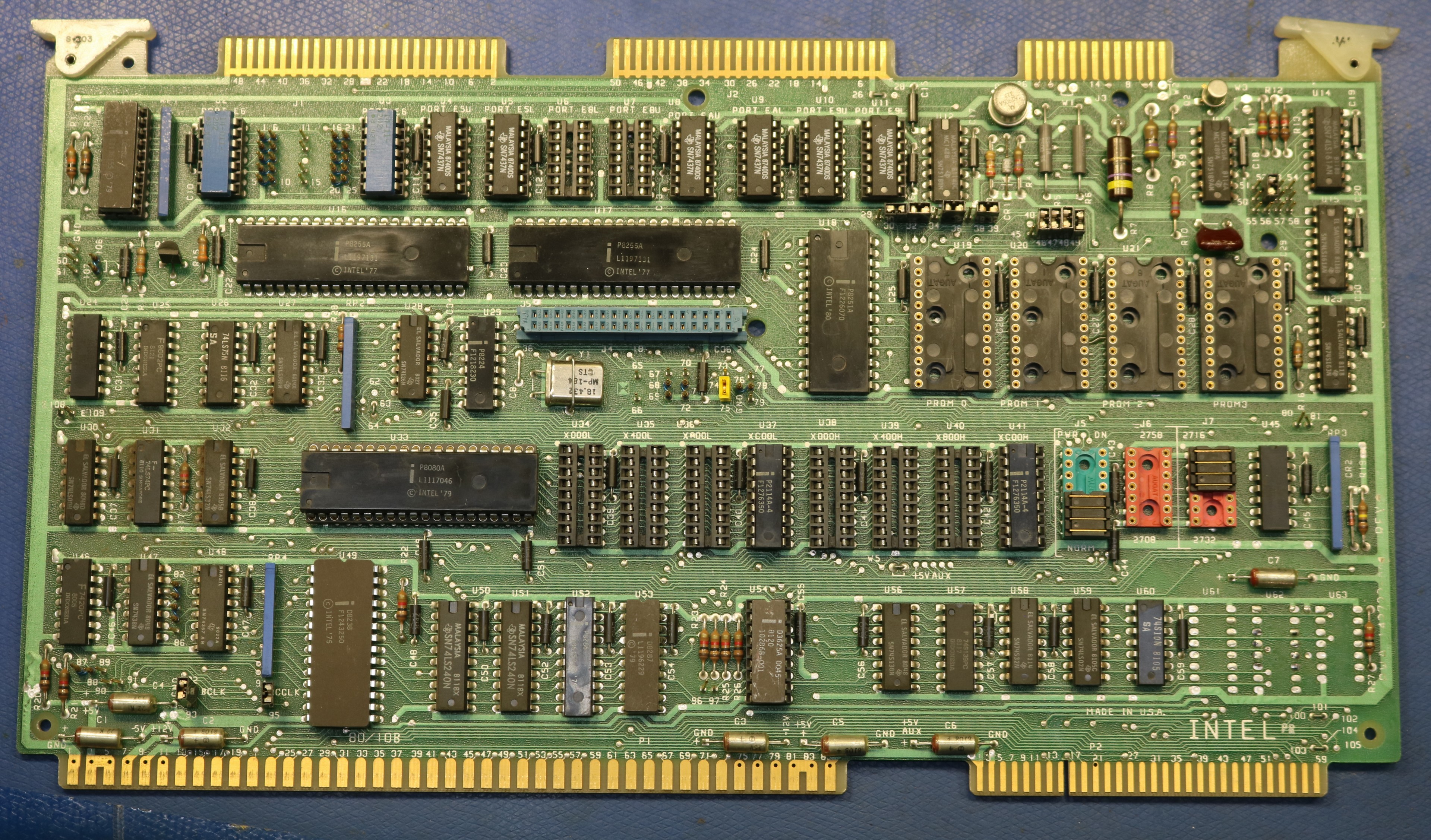
- 80/10, 80/10A, or 80/10B. These are all 8080-based boards, and generally include the 8080 CPU, 48 bits of parallel IO, and serial connectivity using an 8051 UART. The early versions do not have a multimodule socket, but the later versions (like the 10B) do. The available RAM and ROM are tiny.
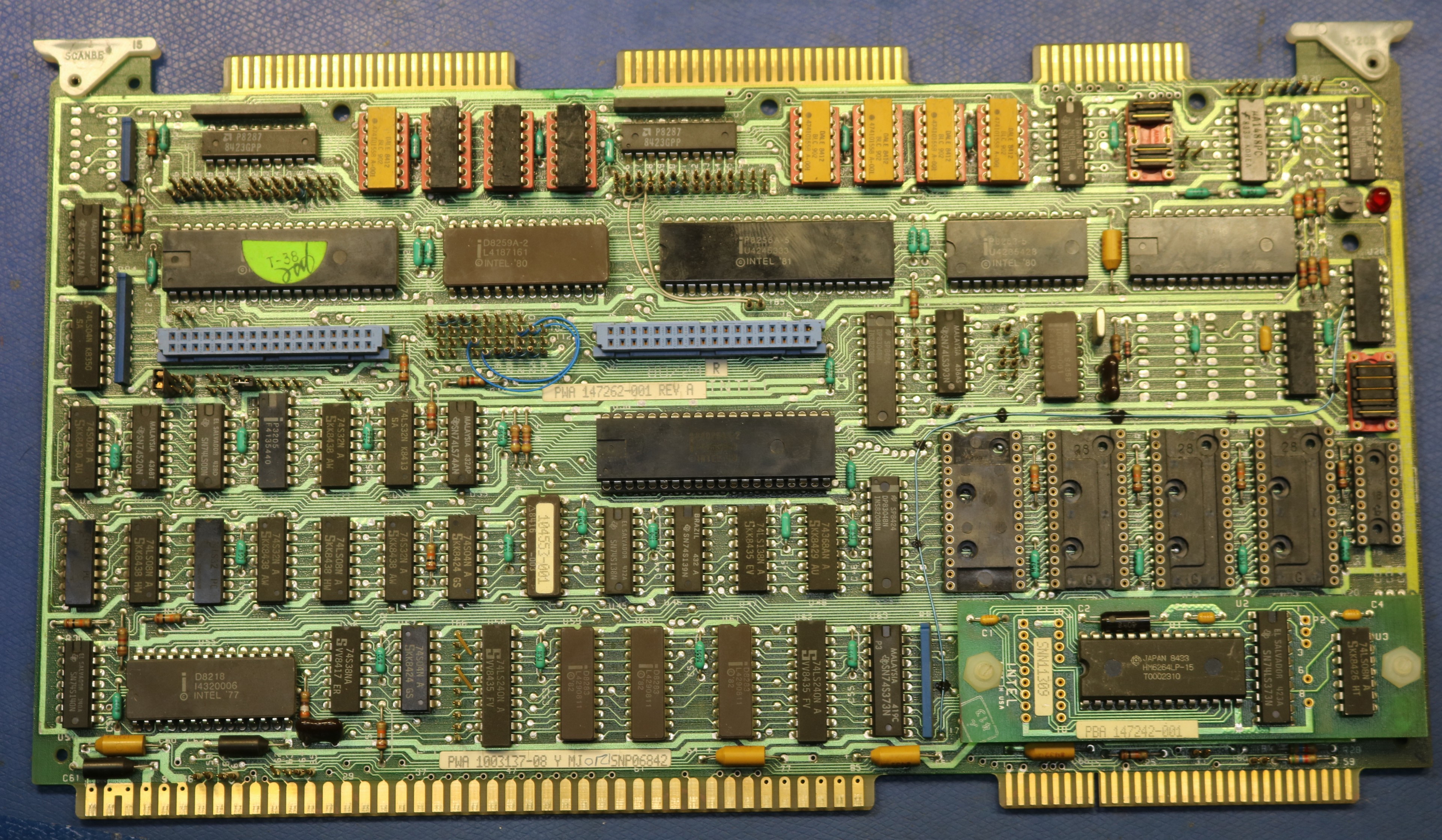
- 80/20 or 80/20-4. These are also 8080-based boards, but they add an 8259 interrupt controller and an 8253 timer that can be used for baud rate generation. A little more RAM and ROM capability.
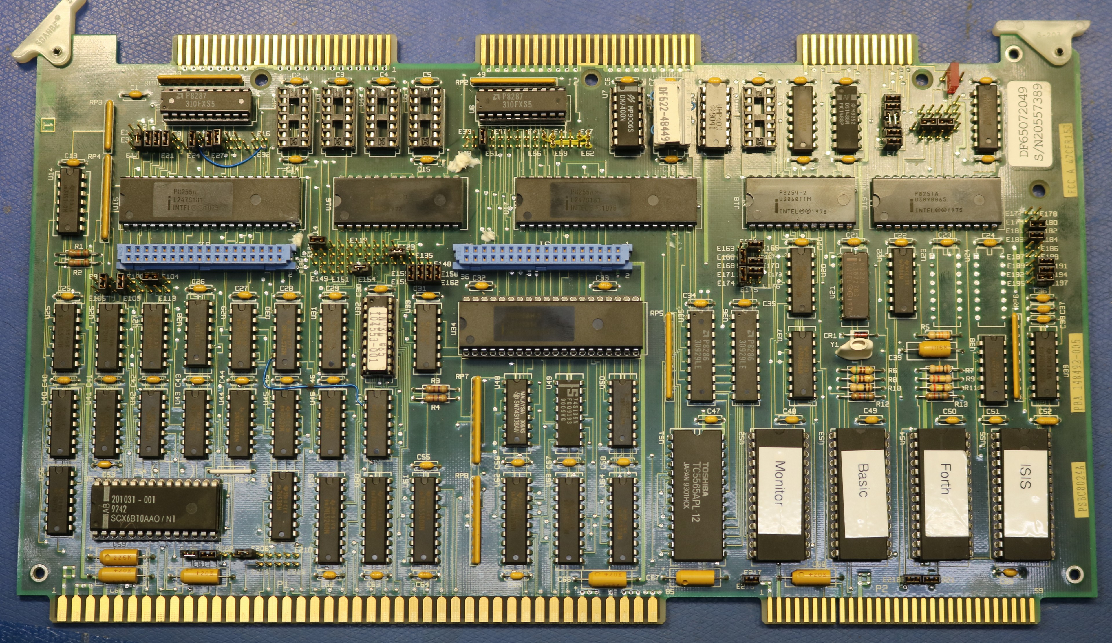
- 80/24 or 80/24A. These are functionally equivalent to the 80/20-4 but using an 8085 CPU instead of an 8080. A little bit faster. Up to 8K of RAM and up to 32K of ROM onboard. Two multimodule slots.
I’m a fan of the 8085, having used it to create an H8 CPU board a few years ago, so I decided to go with the 80/24A. Having the 8259 and the 8254 is nice. There’s a CP/M application note that directly explains how to run CP/M on an 80/24A.
If you get to choose between the 80/24 and the 80/24A, I would recommend going with the “A” because the manual that you’ll find online matches the “A” version, and the jumpers are numbered differently between the two boards. There are a lot of jumpers, and you will most likely need to reconfigure some of them, especially if you bought a used board.
Below are some close-ups of the boards described above:
What can you do with just the CPU board?
An 80/24 offers a generous 32K of ROM/EPROM capability, so I you can quite a bit. I managed to run a monitor, together with BASIC and FORTH, all stored in ROM, with no OS needed. You don’t even need a backplane for this — you could simply wire up power to the SBC and plug in your serial terminal and go. A limiting factor was the 8KB or RAM on the 80/24A. That was enough to run FORTH but only just barely (I had to copy FORTH from ROM to RAM to run it, using most of the 8KB).
Adding More RAM
To run ISIS-II or CP/M, you’re going to need more than 8KB of RAM. 32K might do, but it makes the most sense to go to a full 64KB of RAM.
There are a plethora of existing multibus RAM boards, and you can find many of them listed in Joe’s web page. I managed to score a decent deal on an “028” board, which featured 128KB of RAM (only 64KB is needed, but the extra doesn’t hurt). You can also find 64KB boards, or if necessary you could pair up a couple 32KB boards. Finding an existing board is one path.
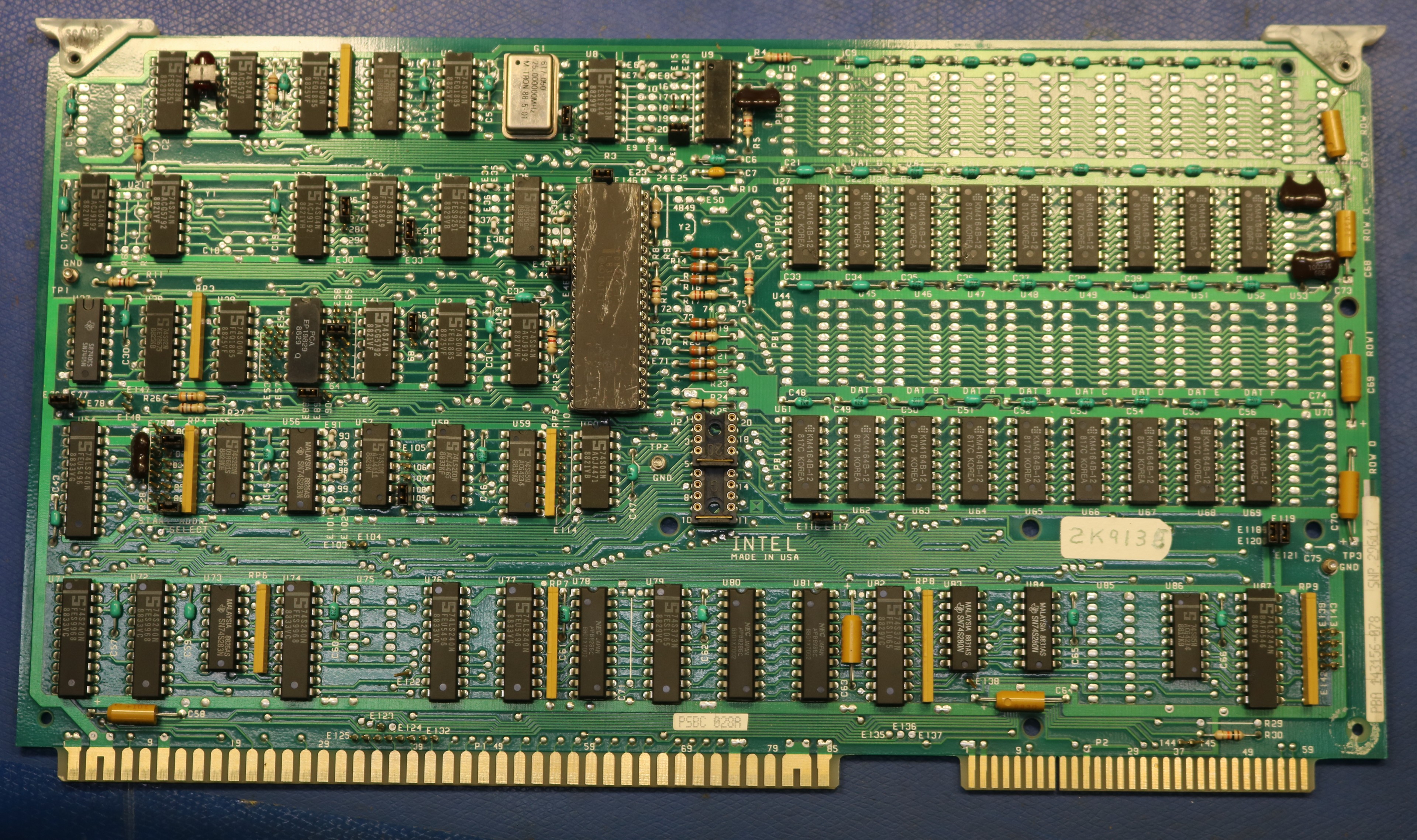
If you can’t find an existing board, then you could build your own. I ended up doing that anyway, creating a combined ROM/RAM/IOC board. We’ll talk about that board later.
Adding a disk
There’s several different options for disks:
- Series II IO Controller (“IOC”). This board includes an additional 8080 CPU and offloads work from the main CPU for terminal (keyboard and video) as well as a single single-density 8″ floppy drive, approximately 250 KB in size.
- SBC-201/202 two-board floppy controller. This is a two board set that implements an 8″ floppy controller, capable of controlling multiple floppy drives. There are both single density (SD) and double density (DD) versions available. One of the boards uses the 3000-series bit slice CPU chipset to implement the floppy controller, and the second board is the interface circuitry.
- Zendex ZX-200A. This is a single-board implementation of the same functionality as the SBX-201/202 board set. It uses an 8085 rather than the bit slice CPU.
- SBX-218 floppy controller multimodule. As far as I know, this can be used for CP/M, but not for ISIS.
What I chose to do was to build my own IOC board. Rather than using an 8080 CPU for the IOC, I used a raspberry pi, and rather than using a physical floppy drive, I served floppy images from the Raspberry Pi’s internal SD card.
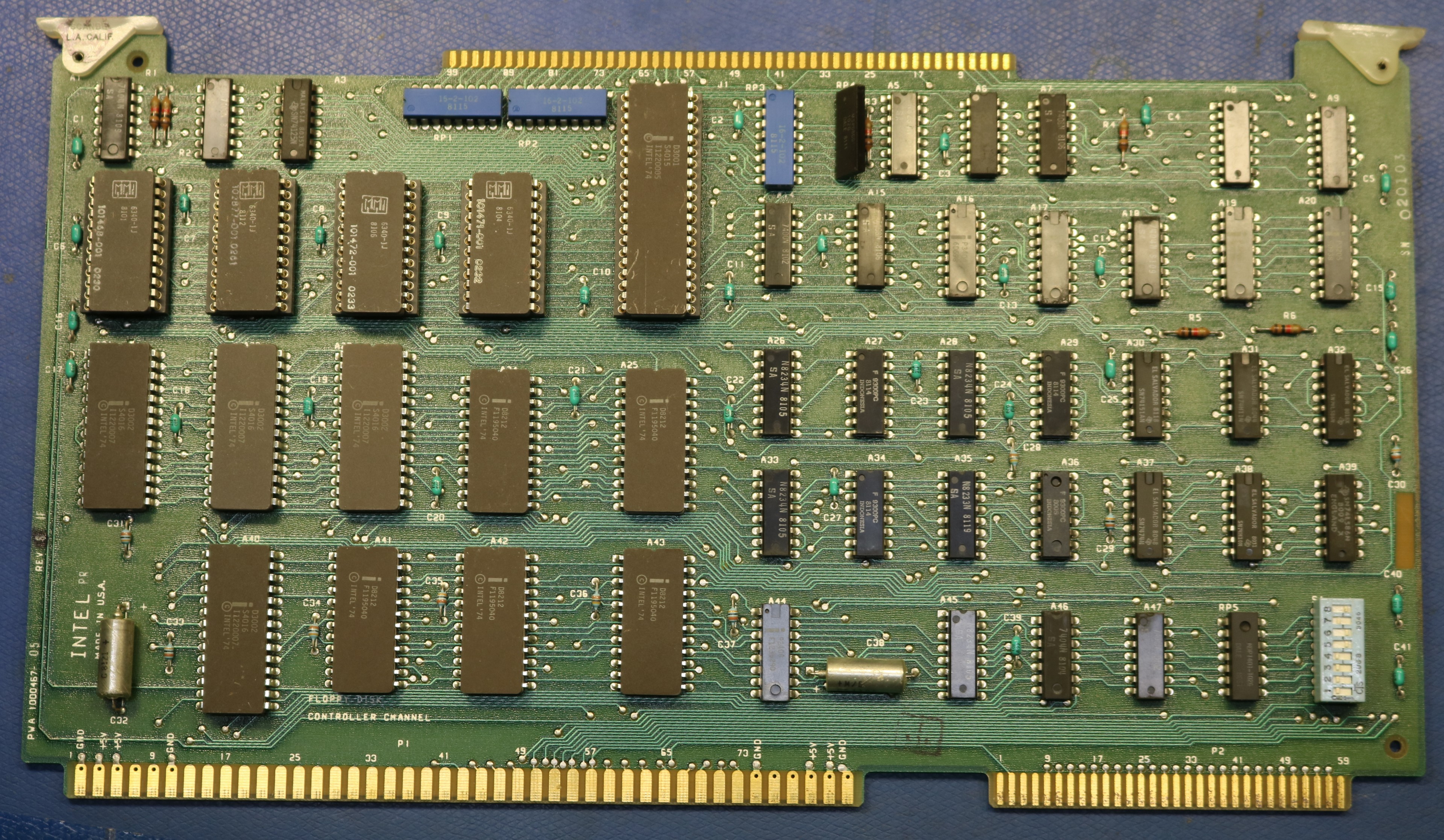
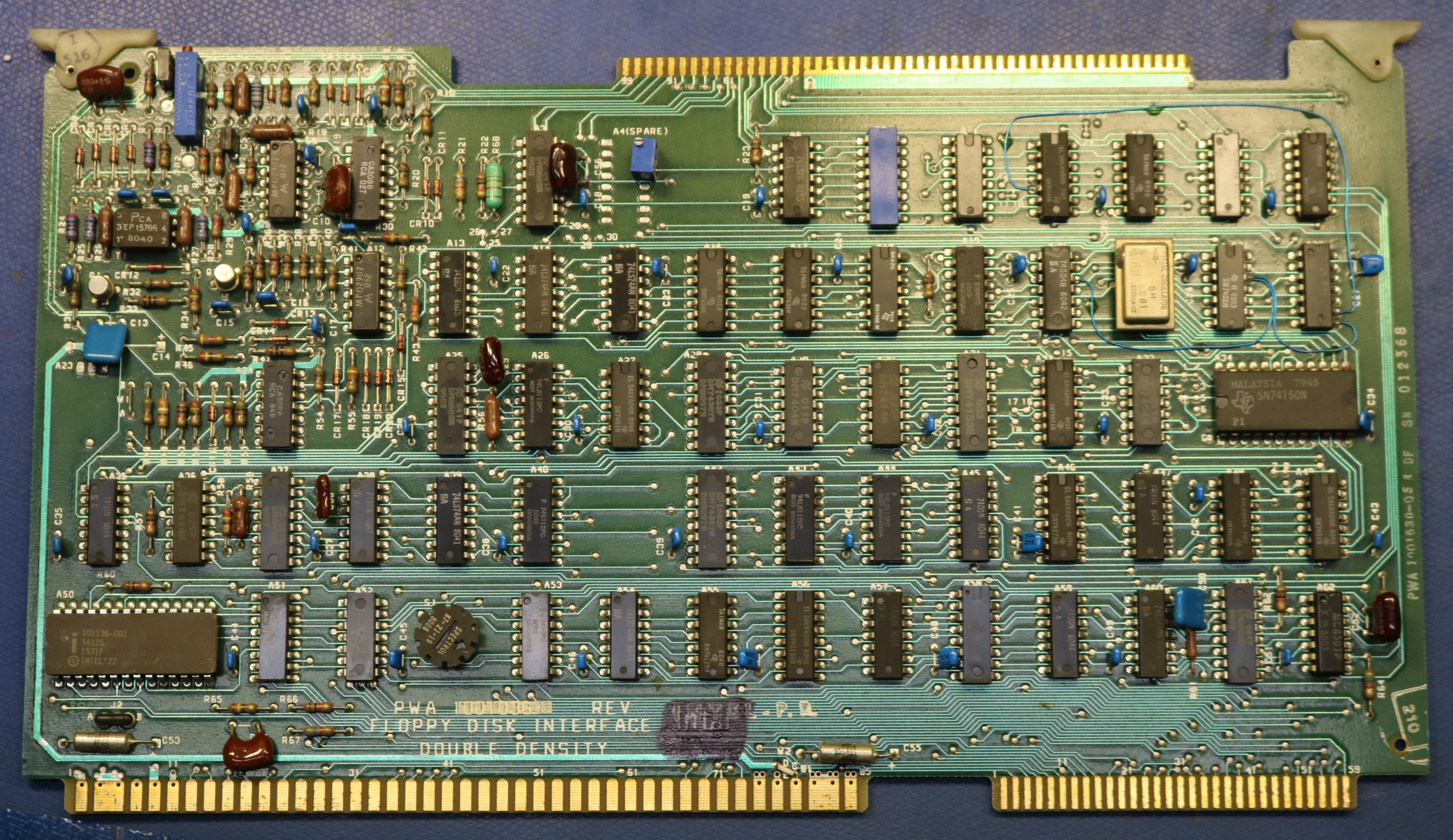
I made my own IO Controller (IOC) Board!
I decided to build my own IOC Board. The IOC Board is the board in the Series II that supported Terminal (Keyboard + Video) and one single density 8″ drive. It did this using its own 8080 processor together with its own RAM, ROM, and a simple 8-bit IO port interface between the IOC and the primary processor.
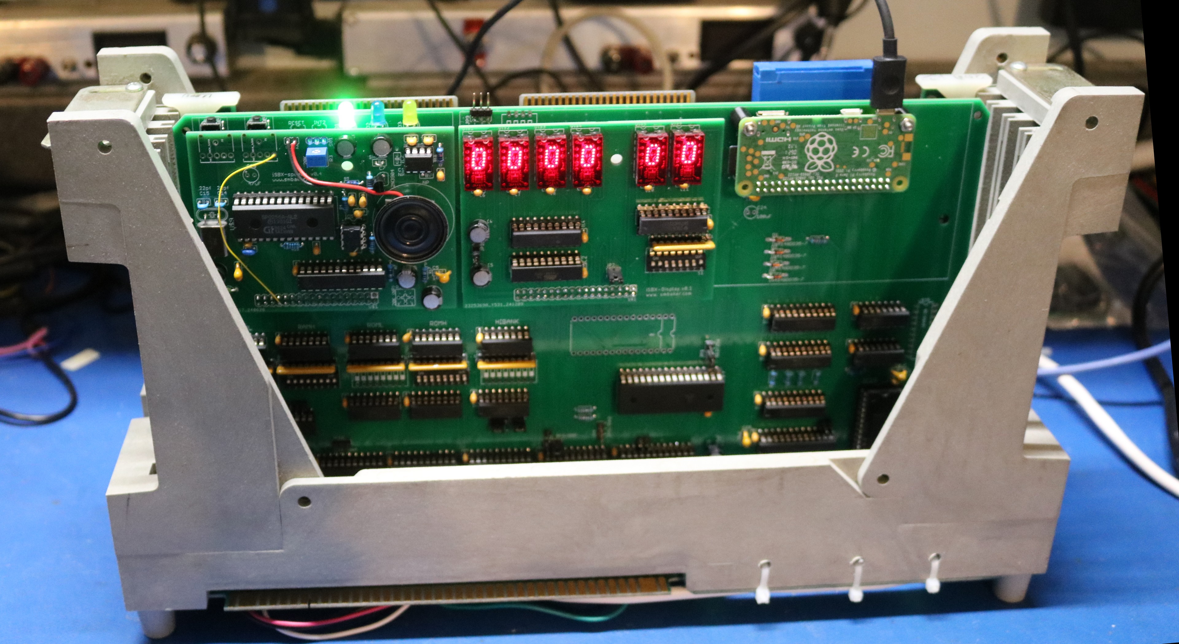
I decided to design my own board, using a Raspberry Pi. I want to stress that the primary CPU in the vintage computer is still the 8085 on the 80/24A board, and all of the original peripherals (serial port, parallel ports, counter/timers, interrupt controller, RAM/ROM, etc) are still there. It’s only the IO controller that uses a raspberry pi, and it only does this to provide a disk interface. Below is a picture of my board:
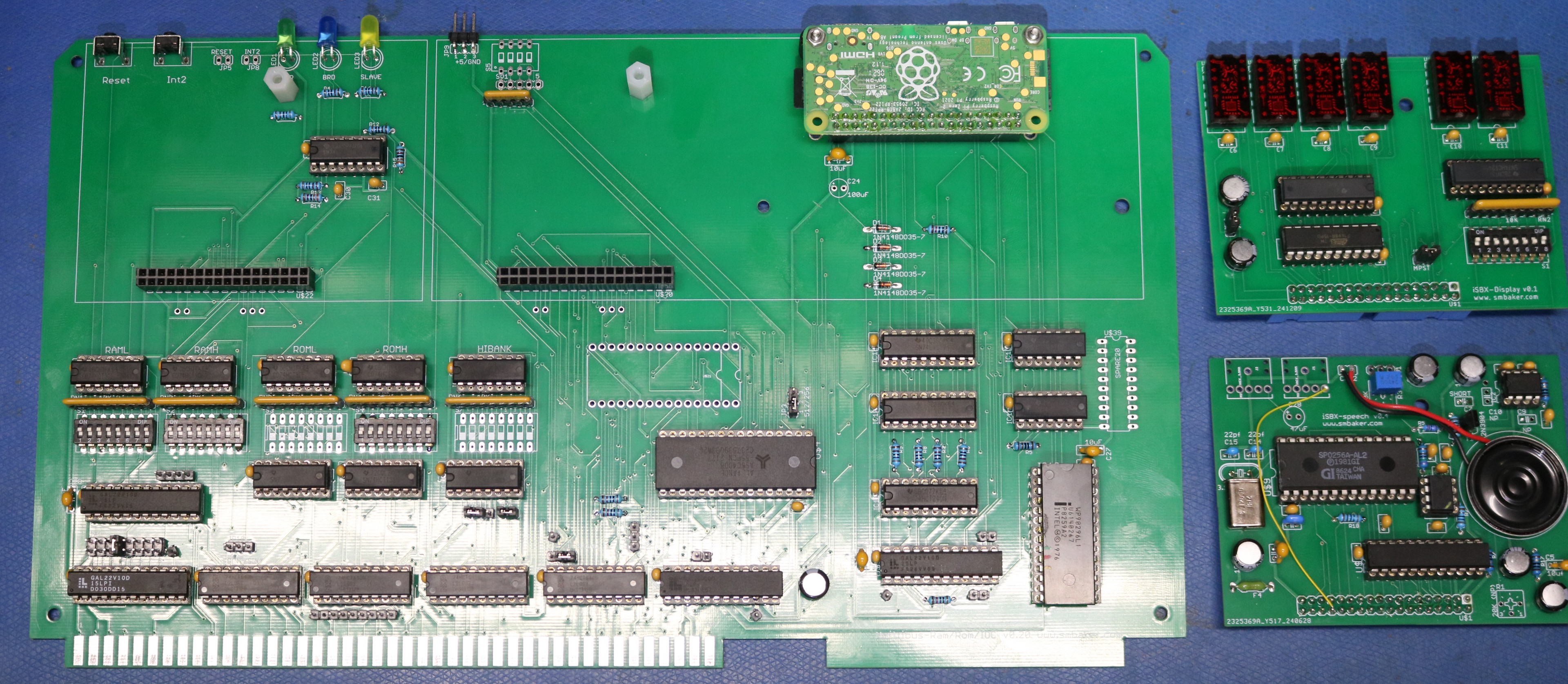
My board supports the following:
- Up to 512KB of system RAM using an AS6C4008. System RAM is optional — you can disable it and use RAM on another multibus board for system RAM instead.
- Up to 512KB of FLASH/EPROM, with 64KB usable selected via dispswitch. This is also optional, and gives you the ability to use a single modern FLASH or EPROM, like a 32SF040 instead of the 4 sockets on the CPU board.
- Two multimodule slots. This is handy because the multimodule slots on the 80/24A board are at addresses that are incompatible with the Series II.
- IO Controller using a raspberry pi, with an 8-bit parallel interface. This makes use of some 74LVC373 latches, some 74HCT74 flip-flops for synchronization flags, a 74LS240, and some glue logic in a GAL22V10D. The whole interface (latches, flip-flops, etc) is straight out of the Series II manual.
In the picture above, I also show a couple of my custom multimodules. One of them is a TIL311 display module which is great for debugging, and the other is a SP0256A-AL2 speech synthesizer.
Modifying the ISIS Boot Loader
The ports in the series II conflict with the ports in the SBC 80/24 CPU board that I chose. For example, the series II places its 8259 interrupt controller at ports FA/FB whereas the 80/24 places them at ports DA/DB. Worse yet, the F0-F9 range on the 80/24 is dedicated to the multimodule slots. Similarly, the 8251 ports didn’t match, nor did the 8254 counter/timer ports.
This meant I had to make a custom version of the ISIS-II boot loader that used different port addresses.
Resources
- 8080-Monitor Github Repo. This is my fork of imsaiguy’s 8080 monitor to add a few features, such as launching Basic, Forth, or ISIS from ROM.
- Multibus Projects Github Repo. This is the repository where I put general multibus stuff, including the design files for the combination RAM/ROM/IOC board that I used in this article. The software for implementing the IOC protocol on the raspberry pi is here.