In this post, I design my first TMS5220 speech synthesizer module.
Purpose
The TMS5220 is one of those chips that has interested me, but I’ve never had a chance to design my own circuit based on one. I did have some experience with the HP 27201A speech synthesizer module, and Echo II Speech Synthesizer (for the IBM PC, not the much more common Apple card!), but these were both pre-assembled commercial products. I’ve often thought of building my own.
At the same time, I’ve been implementing multimodules for my multibus computer and paying particular attention to speech synthesizers. I have multimodules for the SP0256A-AL2, Votrax SC-01, and the Digitalker. Now I have made one for the TMS-5220 speech synthesizer too!
Background
The TMS5220 is a Linear Predictive Coding (LPC) speech synthesizer. The TMS5220 followed the TMS5100. Speech is divided into frames, and each frame has 12 paraneters. The parameters are pitch and energy, and a series of 10 “reflection coefficients”. The parameters are packed and compressed together to fill as few bits as possible, so the frame end up being of varying lengths. Wikipedia can give you a good background on how LPC encodes speech.
The TMS5220 can be operated in two different ways.
- The first method is to use a speech ROM. The popular TMS6100 speech ROM is one example, and there are several different TMS6100 ROMs. The most widely available is the UK ROM, popularized in the BBC Acorn speech synthesizer with phrases spoken by British newscaster Kenneth Kendall. There’s also a US version. Another ROM, the VM71003 contains clock-related phrases and is voiced in a female voice. The UK ROM features 291 phrases! The VM71003 has considerably fewer, only about 35 (you don’t need a lot to say the time). You basically load an address into the TMS5220 and then execute a SPEAK command and it speaks the phrase at that address.
- The other way is called “SPEAK EXTERNAL”. Rather than use a ROM, you send the LPC data byte by byte from the host computer. This gives you a nearly unlimited vocabulary, but it’s obviously more compute intensitve for the host CPU, which needs to frequently be tending to the speech synthesizer by sending bytes to it.
There are also a few supporting functions, such as the ability to READ data from the ROM. This is useful to dump the contents of a ROM.
Interfacing to the TMS5220
The interface is relatively straightforward, 8 data bits, a read strobe, a write strobe, a ready/wait signal, and an interrupt. Easy fodder for an 8-bit project.
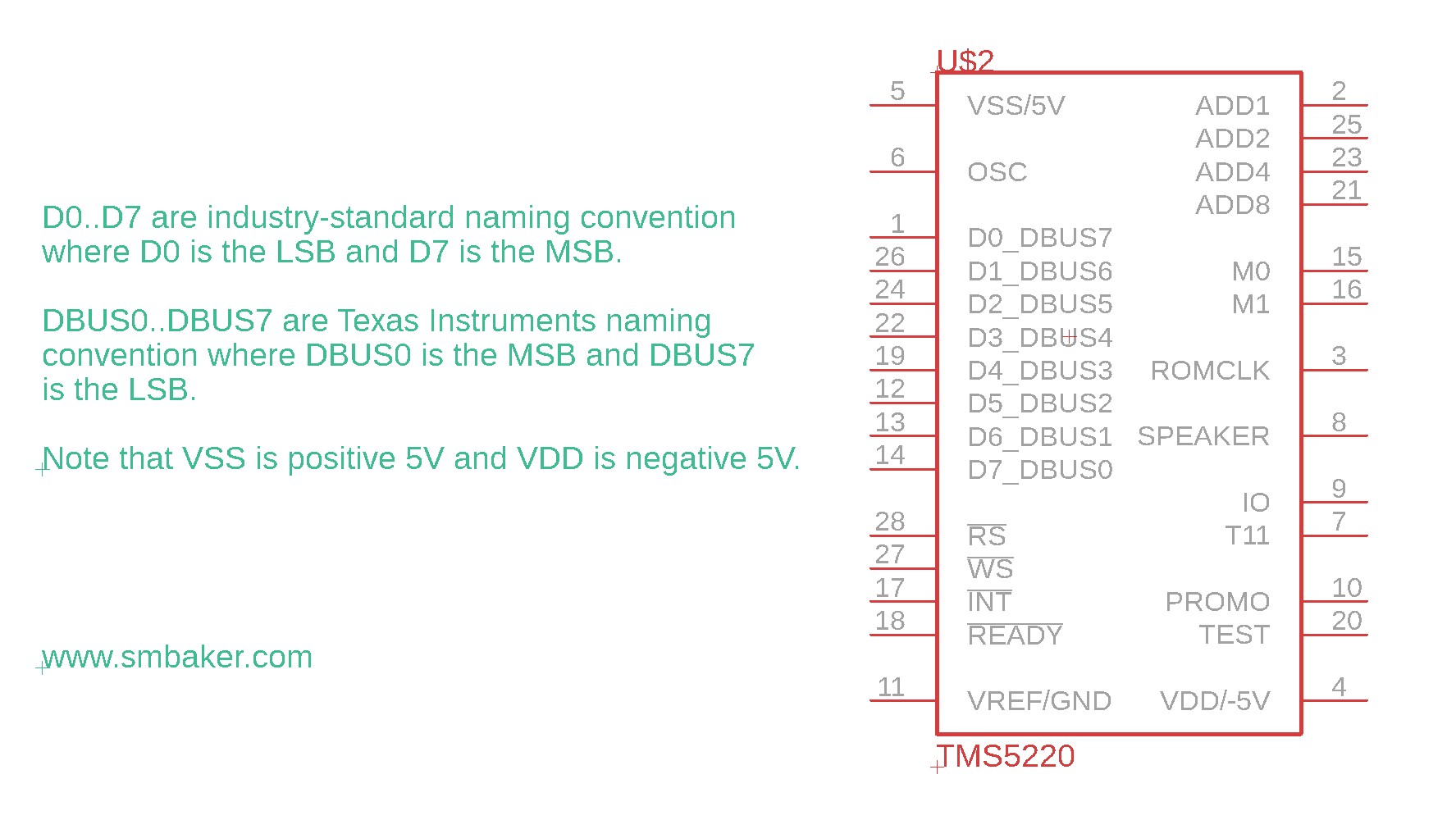
Super Important Note! Unlike almost everyone else in the computer industry, TI decided to make D0 the most significant bit and D7 the least significant bit. This will constantly make your brain hurt while you’re dealing with this chip.
Basically you put your data on the bus, pull the WS low, wait until !ready is false again, then you release WS. Same procedure for reading with RS.
The TMS5220 is a “slow device”
The datasheet says the TMS5220 is slow and it’s not kidding. The speech synthesizer has a !READY signal which you must implement. !READY goes high when you issue a command or write or read data to/from the speech synthesizer. The data bus needs to remain dedicated to the TMS5220 while in this state. This led to a lot of my struggles with getting the IC to work initially. The multibus has a 10 millisecond timeout on the XACK line — if a IO transfer is not completed in 10 milliseconds the multibus host will acknowledge it itself and move one — and many times I had transactions to the TMS5220 taking in excess of 10ms. Such long transfers are usually due to sending a command while the speech synthesizer is busy. It will make you wait until the command is complete.
If you do not implement these wait states, then things may go wrong — very wrong. In one of my examples I did not implement the wait properly and while I was trying to READ from the chip, it was occupying the data bus while I tried to write to my serial port. Why isn’t the serial port working??? Because the TMS5220 was occupying the bus. Get the wait states to work right, and use an oscilliscope or logic analyzer if you’re not sure you’re doing it right.
Schematic
Note: all of the schematics are available in my github repo in PDF form where you can zoom in and see clearly.
I’ve decomposed the schematic into three sections:
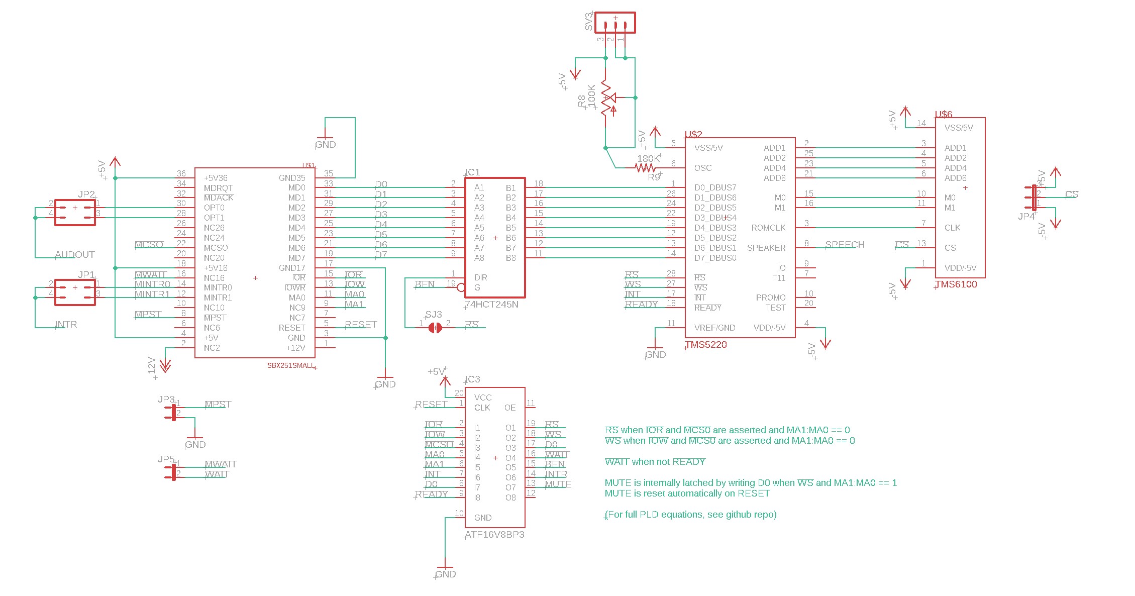
Above is the digital portion of the speech synthesizer. From left to right we have the 36-pin multimodule bus connector, a 74HCT245 buffer, the TMS5220 speech synthesizer, and the TMS6100 optional speech ROM. A ATF16V8 programmable logic device is used to decode the !RS and !WS read and write strobes implementing some simple logic. It also inverts !READY to turn it into !WAIT and it implements a latch to hold the MUTE signal. Next up is the power supply.
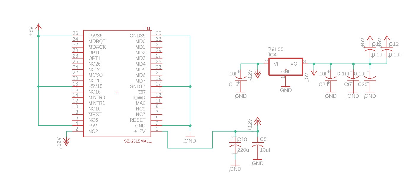
Above you can see the power supply. It’s relatively simple. The TMS5220 needs -5V, and the multimodule connector has -12V, so I used a 79L05 minus five volt regulator. Finally we have the audio section below:
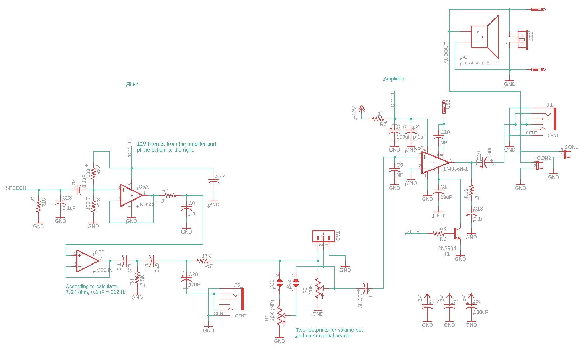
Above left if the filter and above right is the audio amplifier. The filter is Scott’s “don’t know what I’m doing filter” where I basically took a low-pass filter and a high-pass filter and added a couple op-amp unity buffers. I’m sure someone who knows what they’re doing can do better. It’s important to have a DC bias on the input to the op-amp, and C14 decouples the input where it goes to a resistior divider (R22, R23) that centers the signal at about 6V, right in the middle.
From out of the filter, we go through a volume control (two footprints for the pot, to support different board orientations) and then into a LM386 audio amplifier. We come out of the LM386 and into a jack and some speaker headers.
Note that my standard mute circuit is here. If you pull down pin 7 of the LM386 you will mute it. The mute signal is driven by the PLD in the digital section of the schematic.
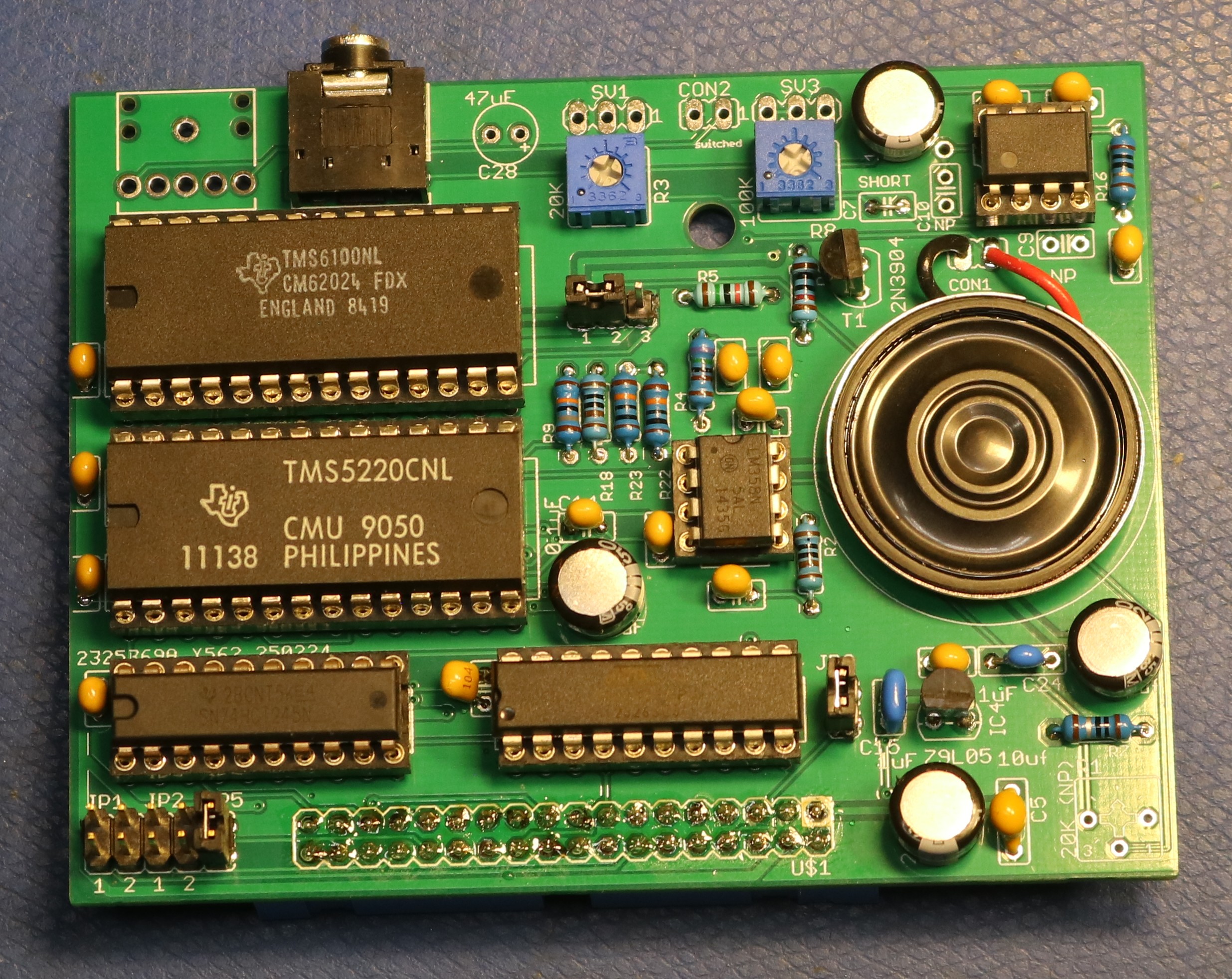
Building the board
A picture of the board is below. It pretty much exactly folows the schematic.
Software
I wrote a demo program that runs under the ISIS-II operating system on my multibus computer. It’s standard 8080 assembly. The code is all in my github repo, but I’ll share a few excepts below.
First let’s talk about using the SPEAK command to speak from the speech ROM. Before we can speak, we first have to send the address and that is the job of the TMSADR subroutine:
	; TSMADR - set address to rom
	;  BC = addr
	;  Destroys A

TMSADR: MOV	A,C
	ANI	00FH
	ORI	040H
	OUT	TMSOUT	; A0...A3
	MOV	A,C
	RRC
	RRC
	RRC
	RRC
	ANI	00FH
	ORI	040H
	OUT	TMSOUT ; A4...A7
	MOV	A,B
	ANI	00FH
	ORI	040H
	OUT	TMSOUT ; A11..A8
	MOV	A,B
	RRC
	RRC
	RRC
	RRC
	ANI	00FH
	ORI	040H
	ORI	((ROMADDR shl 2) and 0CH)
	OUT	TMSOUT	; A12, A13, CS0, CS1
	MVI	A,040H
	ORI	((ROMADDR shr 2) and 03H)
	OUT	TMSOUT  ; CS2, CS3, x, x
	RET
After sending the address, the next job is to initiate the speak command, which is nothing more than sending a 050H out to the speech synthesizer. We also need a function that can wait for the speech synthesizer to be idle, unless we want to WAIT for a long while. Here’s TMSWRD that wraps speaking-from-ROM all together:
	; TSMWRD - say word in ROM
	;  BC = addr
	;  Destroys A

TMSWRD:	CALL	TMSWAT
	CALL	TMSADR
	MVI	A,050H
	OUT	TMSOUT	; Speak
	RET

	; TMSWAT - wait for TMS to be idle
	;   destroys A

TMSWAT: IN	TMSIN
	ANI	080H
	JNZ	TMSWAT
	RET
Speaking from the host computer with SPEAK EXTERNAL is a little bit more complicated. Following some recomendations on an Internet forum, I do the following:
- Initiate SPEAK EXTERNAL by writing 060H out to the synthesizer
- Send the first 16 bytes. This fills up the FIFO. It’ll start speaking on the 9th byte.
- For each subsequent block of 8 bytes, wait for the FIFO to become half-full. This ensures we have room for 8 more bytes.
- If there are remaining bytes, fewer than 8, send those at the very end
	; TMSEXT - speak external
	;
	; DE contains speech data. First word is the length.
	;
	; Following guidelines on the Internet, we send 16 bytes to start. Then
	; everytime the buffer becomes less than half full, we send the next 8
	; bytes. There might be a remainder if the number of bytes is not divisible
	; by 8, so we send that too.
	;
	; Note: Assumes length is less than 256 bytes. Fix this as soon as we encounter
	; a bigger sample...

TMSEXT:	CALL	TMSWAT		; wait for not speaking

	MVI	A,060H
	OUT	TMSOUT

	LDAX	D		; get length into C
	SUI	010H		; We always send at least 16 bytes so subtract 16
	MOV	C,A
	INX	D
	INX	D

	MVI	B,16		; send the first 16
TMSXL1:	LDAX	D
	OUT	TMSOUT
	INX	D
	DCR	B
	JNZ	TMSXL1

TMSXL2:	IN	TMSIN		; wait for buffer less than half full
	ANI	040H
	JZ	TMSXL2

	MOV	A,C
	ORA	A		; no bytes remaining?
	RZ
	CPI	08H		; less than 8 bytes remaining?
	JC	TMSXL4		; yup...
	SBI	08H		; nope... so subtract 8 and send the next 8
	MOV	C,A

	MVI	B,8		; send 8 bytes
TMSXL3:	LDAX	D
	OUT	TMSOUT
	INX	D
	DCR	B
	JNZ	TMSXL3

	JMP	TMSXL2		; go to next 8-group

TMSXL4: MOV	B,C		; less than 8 bytes left in C
TMSXL5:	LDAX	D
	OUT	TMSOUT
	INX	D
	DCR	B
	JNZ	TMSXL5

	RET			; we are done -- return
Finally, here is what a blob of speech data looks like for the SPEAK EXTERNAL subroutine. This is me saying my name. I used audacity to record my voice to an 8KHz 16bit wave file, then a program called python_wizard to convert it to TMS5220 speech data. It’s not perfect, but as you can hear in the video, it is at least intelligible:
SCOTT:
	DW	LSCOTT  ; first word is the length
	DB      000H,000H,000H,080H,080H,0dfH,0a6H,009H
        DB      0f0H,04bH,025H,001H,07eH,0aeH,060H,0c0H
        DB      02bH,099H,004H,0f8H,0d9H,083H,001H,03fH
        DB      07bH,008H,0e0H,0b8H,02cH,081H,04eH,05dH
        DB      02eH,0e1H,0a9H,001H,050H,033H,054H,089H
        DB      0a5H,0c5H,011H,069H,032H,02aH,05dH,01eH
        DB      037H,034H,031H,088H,077H,06bH,0c5H,0d0H
        DB      084H,062H,091H,0a5H,0a5H,05cH,017H,09bH
        DB      0a7H,0a7H,00fH,076H,05dH,09cH,0e1H,0d6H
        DB      05eH,0d8H,0f5H,071H,085H,06bH,067H,0e1H
        DB      0d0H,0c7H,019H,021H,09dH,045H,042H,01fH
        DB      067H,084H,076H,016H,071H,043H,09cH,019H
        DB      0daH,019H,038H,08cH,071H,064H,068H,07bH
        DB      090H,030H,0c6H,011H,061H,0edH,081H,0c3H
        DB      014H,05bH,084H,0b7H,007H,00eH,04bH,02aH
        DB      011H,0d9H,051H,0d0H,03dH,031H,086H,0d7H
        DB      044H,029H,0e6H,084H,094H,051H,013H,095H
        DB      051H,098H,073H,0baH,0a5H,085H
LSCOTT	EQU	$-SCOTT
Resources
- You can find the gerbers, schematics, PLD equations, etc in my multibus github repo, here.
- Assembly source code is in another directory in the repo, here. In particular, see the following files:
- tms.asm – demo program
- tmslib.asm – library for TMS5220 functions
- vm7dat.asm – dumped data from the VM71003 clock/calendar speech IC
- vm7tim.asm – library functions to use vm7dat to say “the time is X:Y AM|PM”