I started a project to build a self-balancing 2 wheel robot today, based largely on Hanno’s Propeller-based dancebot from the new propeller book. The first step was sourcing sensors, and the first sensor I decided to work on was the accelerometer, the LIS3LV02DQ.
This accelerometer is a 3-axis using and can communicate digitally via I2C or SPI. It can be interfaced to the prop with no external components (well a couple of bypass caps are usually a good idea) which make it pretty easy. It’s cheap, about $10/chip from newark. The problem is…. it’s a 28-pin QFN surface mount package, and I’m not a surface-mount person. The QFN package does not have pins; it just pads underneath the chip. This makes it a little more troublesome to hand-solder than some of the other SMT devices that do have pins.
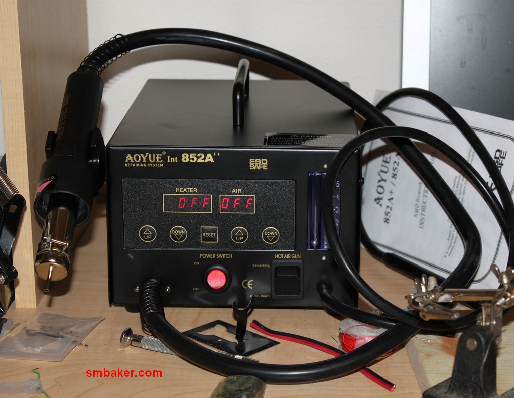
So, it seems like the appropriate time to dive into surface mount work. I started by getting a hot air gun, an Aoyue 852A++ rework station for sra-solder.com. It cost $139 plus shipping, which came to just over a hundred and fifty bucks shipped. Seems like a bargain. The hot air station is chinese made, but the brand has good reviews on amazon and elsewhere. It features digital controls and also sports a built-in vacuum pickup tool. Here’s a picture of the rework station:
Above is a picture of the station sitting on my very cluttered workbench. There’s two toggle switches. One is a master on/off and the other switches between hot air and cooldown modes. The buttons are used to adjust temperature.
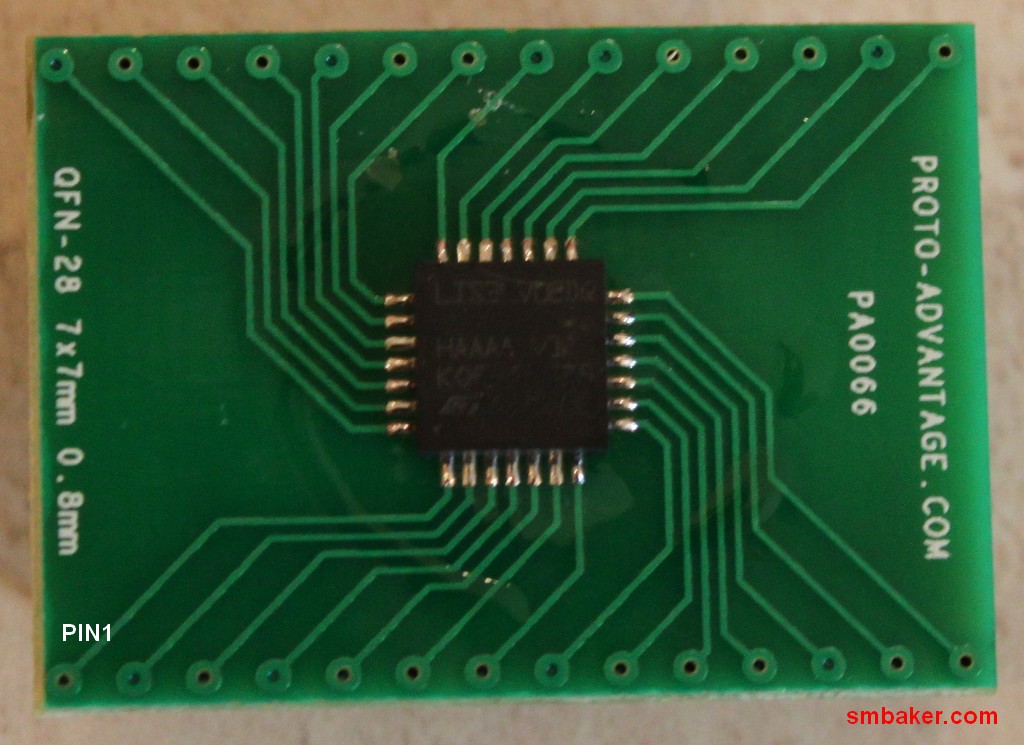
In order to breadboard the accelerometer, I got some QFN28-to-DIP adapter boards from Proto Advantage. These are little circuit boards with the QFN28 pattern on the top and a DIP pattern for standard 0.100 headers on the bottom.
I started by applying some solder to the pads on the board. Cleaned it up a little bit to make sure that I didn’t bridge any of the traces. Applied some flux to the board. Set the QFN28 chip on the board using some tweezers and aligned the pins as well as my eyesight permitted.
After that, I fired up the hot air station to 400 degrees with an air setting of about 12. Start swirling around the chip with the hot air until you notice the solder start to melt and flow. Shut down the hot air and let everything cool. It’s as simple as that. I didn’t record the time, but I’d say it took under 30 seconds to do the job.
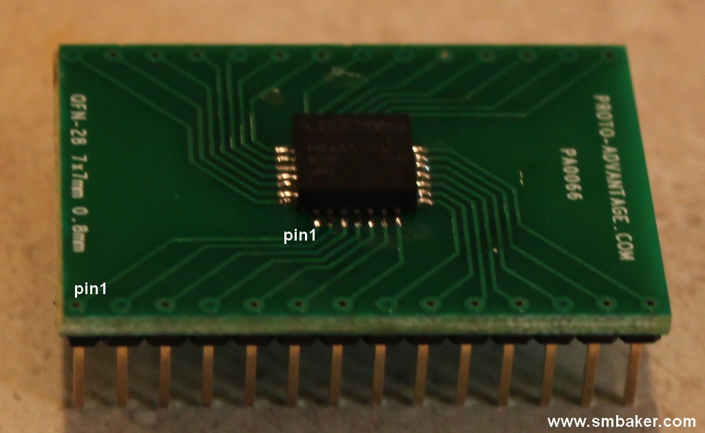
To finish off the Proto-Advantage board, you have to solder the 0.100 headers on the back side. If I’d had some solder paste I think this would have also been a near-instant process. However, all I had on hand was my usual rosin-core throughhole solder, so I hand-soldered the 0.100 headers with my xytronic iron. Here is a picture of the finished product:
Although it kind looks like there are pins in the picture, looks are deceiving. The proto-advantage board has extra-long pads (probably to allow hand-soldering with a regular iron), and you’re seeing the excess solder the flowed out from under the chip back onto the pad. If I’d have used a stencil and solder paste, there probably would have been a lot less excess.
As you may notice, I soldered the chip about 180 degrees rotated from how I probably should have soldered it (the proto-advantage text is upside-down if you orient the adapter with pin1 toward the top). Fortunately, it doesn’t really matter. I’ll just mark pin1 on the adapter with a white dot or some such thing. If that’s the biggest mistake I made on my first SMT attempt, then I’ll be happy.
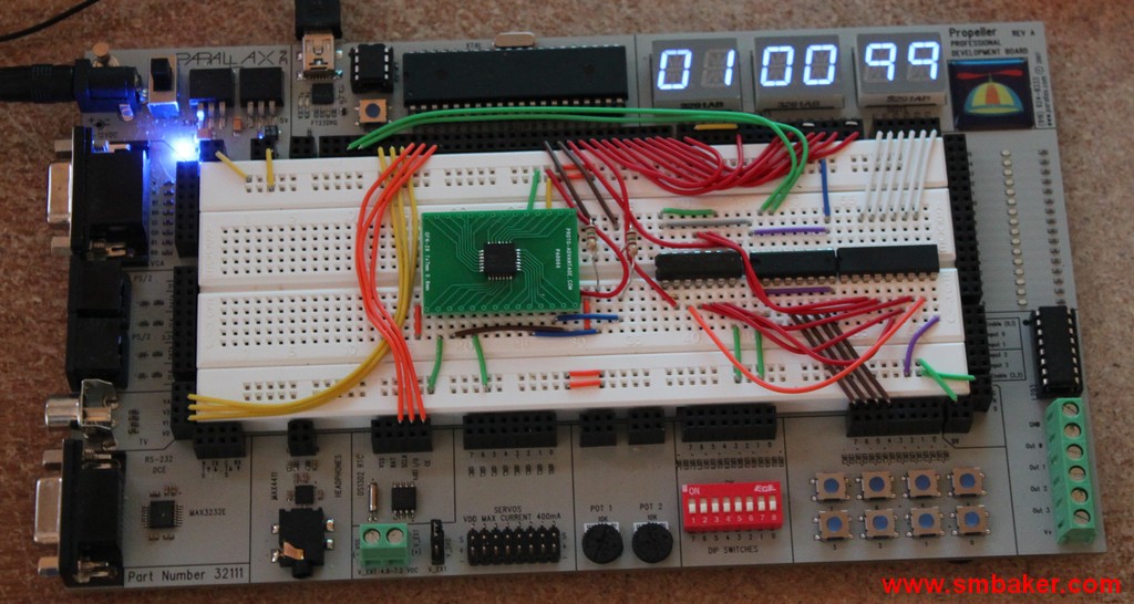
The next step was to put this thing on the propeller proto-board and see how it works:
I have the three LED displays showing the acceleration on the X, Y, and Z axis respectively. The Z axis points straight up. The X axis runs from the bottom to the top of the proto-board, and the Y axis runs from the left to the right of the proto board. Although it’s indicating 99 (9.9G) on the Z axis, it’s actually measuring 1.0G; I capped it at 9.9 to fit the measurements on the 2-digit display. The X axis is reading 0.1G, probably indicating my computer table is not level. As you tilt the board, the numbers change in the predictable way.
Well that’s it for this post; my SMT attempt was a success. The Aoyue 852A++ hot air station was very easy to use, and I’d recommend it to anyone looking to experiment with SMT work.


Dear. Mr Scott
I’m working with the propeller and the ST LIS3LV02DQ acelerometer, but I’m having problems.
Do you have a connection squeme expecilly the resistors values in the IO lines? do you have also the code for propeller ? how you connect it, via SPI or via I2C?.
Please help me I’m quite desesperate. You will also gain a friend here in spain.
regars
Ignaco
Hello Ignacio, I think my current design uses 150 ohm resistors. I’m not sure they’re even necessary; I mostly throw them in to prevent overload in case of a programming mistake (prop and peripheral outputting conflicting values on an IO line, etc). I’m using i2c. The schematic and code came from the book “Programming and Customizing the Multicore Propeller Microcontroller”. I think they have the code from that chapter available online at http://ftp.propeller-chip.com/PCMProp/Chapter_06. Look for _Tilt.spin and i2cobject.spin.
Dear Dr. Scott,
I would like to describe to you the problem I am having in using the ST LIS3LV02DQ accelerometer.
By setting properly the values of the control registers, it is possible to select the data rate at which acceleration samples are produced. By changing the content of DF1,DF0 to “00”, “01”, “10” and “11” the selected data-rate will be set respectively equal to 40Hz, 160Hz, 640Hz and to 2560Hz.
For example, if 160 Hz is selected, the accelerometer updates the registers storing the acceleration samples every 6.25 ms.
What I would like to ask to you is: how should I use the accelerometer if I would like to sample at a rate different from the 4 available values? I’ve tried to read the registers from the master MCU at 200Hz (once every 5 ms), and of course what I get is a signal full of repeated samples, since I am reading the registers every 5 ms, but the accelerometer is updating them every 6,25 ms. What if I would like to take a sample exactly at the time the MCU wants, without following the output rate of tha accelerometer?
I would really appreciate your help in solving this problem.
With best regards,
Maurizio.
im trying to do the dancebot also and was wondering if the https://www.parallax.com/Store/Sensors/AccelerationTilt/tabid/172/CategoryID/47/List/0/SortField/0/Level/a/ProductID/97/Default.aspx would be a acceptable alternative to the LIS3LV02DQ so i could avoid the above purchase.also potential problems if i did.
I orderd the parts in the manual.Icant seem to get the above link to work.idk
im good thanks anyway