This post documents my attempt to create a self-balancing robot, based on the “DanceBot” design by Hanno Sander (http://hannoware.com/dancebot). It’s a fun but challenging project. Most of the design information came from the new Propeller Book.
Sourcing Componets –
Gyroscope: GWS-PG-03, Power Hobby
Accelerometer: LIS3LV02DQ, Newark Electronics
Accelerometer Proto-Board: Proto-Advantage
H-Bridges: (2) LMD18200, ebay
H-Bridge proto-boards: Spark-fun electronics
Main Board: Parallax Professional Development Boards
Motor: GHM-16, Lynxmotion
Motor Mounts: Lynxmotion
Motor Rotary Encoder: Lynxmotion
Wheels: Lynxmotion
Robot Chassis: Round alumininum, approx 8.25″ diameter x 3/8″ think, from the junk box at the local metal place.
A couple of the components needed special attention. The LIS3LV02DQ is a SMT package in QFN28 package. I used a proto-board from proto-advantage to adapted it to the usual 0.100″ spacing, soldering it with my hot-air gun. The LMD18200 also isn’t breadboard friendly, but some breakout boards from sparkfun electronics solved that.
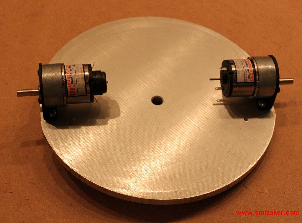
The first step was to build the platform that the robot would sit on. I found a nice round chunk of aluminum approximate 8.25″ in diameter in the junk box at the local metal supplier. It was a little thicker than I wanted, but otherwise fit the dimensions and only cost me two bucks. Made a template using SmartDraw to figure out where the motor mounts would go (and get them square and true), and mounted the motors and mounts to the platform:
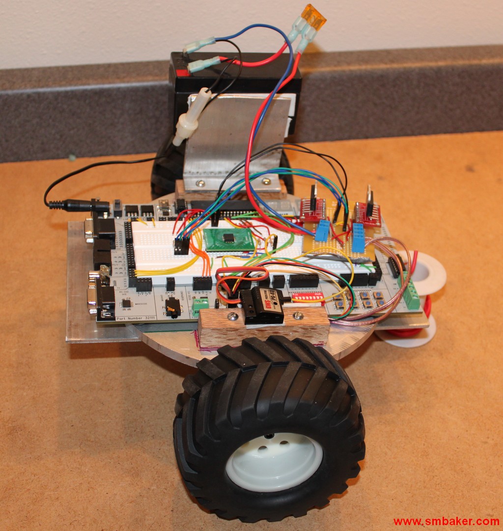
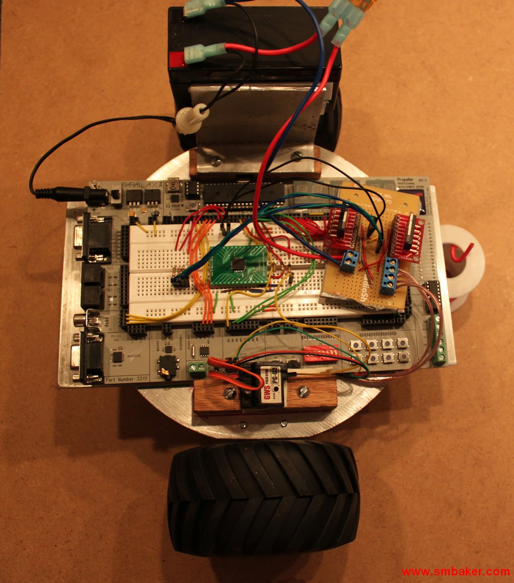
Next, I secured the Propeller Professional Development Board to the top of the platform using a couple of wood blocks. The PDB is only temporary; I’ll probably make a custom board eventually. Constructed a battery bracket from some more aluminum. A couple of pieces of aluminum flat stock were used to make some guard for the PDB so it wouldn’t get smashed if the robot crashed into something. Here are a couple pictures of the initial prototype of the robot:
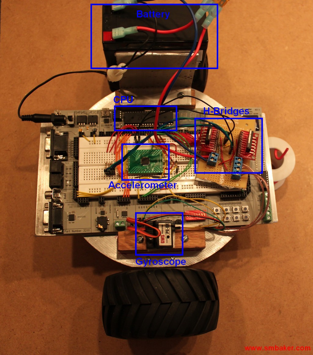
Finally, here is a picture diagramming the major components:
Finally, a link to the youtube video:


May I suggest the addition of a mast with the batteries located at the top. (see original Hanno video) Tall objects fall over very slowly. Hanno placed his camera and his batteries on the top of a mast to allow more time for the system to correct in pitch. The accel. should be located on the top of the mast and the gyro placed as close as possible to the pitch (axle) center line. The accel. is at a serious disadvantage located so close to the pitch axis. Consider, if you place the accel. on the pitch axis it would sense only forward/reverse acceleration generated by the motors, not the acceleration due to the rate-of-change as the robot falls over.
Try this experiment. Take your kitchen broom, place the handle in the palm of your flat open hand. Try to balance the broom (brissels up) by moving your hand as required to keep the broom vertical. With a little practice……. Now try the same thing with a ball point pen.
Just a few loose thoughts over Saturday morning coffee. No offense intended, I hope none taken.
James (jim) Ward
Carrollton Texas
Thanks for the additional information, James. I’ll definitely try placing the battery higher. I had noticed that many balancing robots had a mast, but until now I haven’t understood the physics behind it.
You probably have looked at this site but I pass it along anyway. http://www.balbots.com They have a good box mast “Balance Bot” design. When I found out they were out of business I shamelessly copied the mechanical lay out for a one-off project I have substituted my own electronics. I seem to remember a vidio link showing thir Bot in operation.
Jim Ward
Any chance I can get the code for this? Ive already purchased all of the parts. Id appreciate any help you could give. thanks