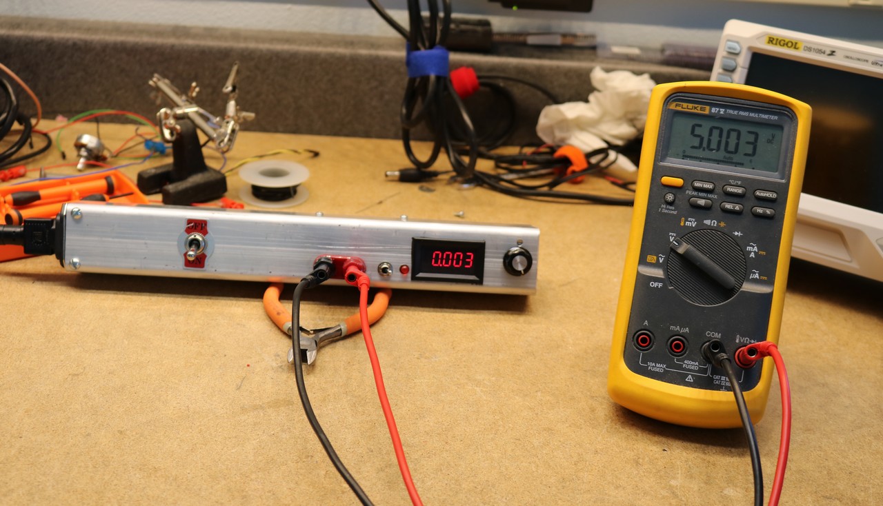
In this blog entry, I describe a constant-current LM2576 power supply. Below is a picture of the supply, mounted into a section of aluminum square tubing.
I already have a nice commercial power supply on my bench, but whenever I need some additional power, such as 5V DV, I end up grabbing a wall wart. While the wall warts work, 1) their longevity isn’t great (several have failed on me), 2) there’s no meter to show current consumption, and 3) there’s no current limiter to keep me from accidentally frying a project if something goes wrong. I decided to finally build my owned fixed power supplies for the bench.
My key criteria were:
- It has to be slim and short, and fit in the space between my workbench my wall-mounted power strip. That gives me about 2″ of height and 2″ of depth to work with.
- It has to have a meter to show how much current is being draw.
- It has to have an easily adjustable current limiter.
I’m a fan of the LM2576 switching regulator, so I decided to give that a shot rather than building one of the more traditional LM317 designs.
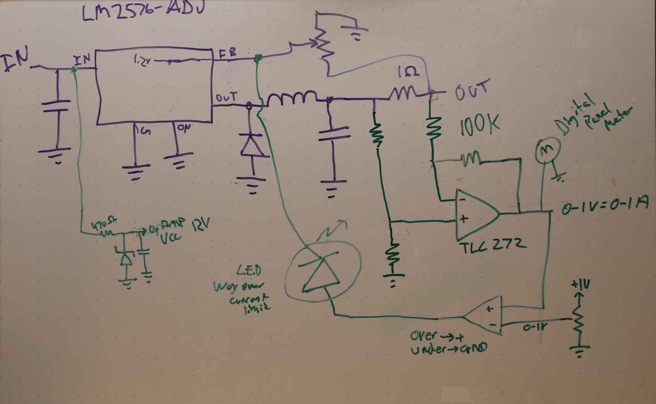
Let’s start by taking a look at the circuit. The following is my hand-drawn schematic on a whiteboard from the youtube video I made of the supply:
Starting at the top-left, we have the LM2576-adj regulator. They make several versions: LM2576-5, LM2576-12, LM2576-ADJ, etc. If you examine the differences in the datasheet, you’ll see that the fixed voltage (-5, -12, etc) regulators include a built-in voltage divider whereas the -ADJ version you supply your own voltage divider. The potentiometer top-center in the schematic will serve as our voltage divider. Although I’m building a fixed 5V supply, we’ll see that having the voltage divider external comes in handy when we go to add the current limiting feature. In my reference build, I used a board-mounted 10-turn pot.
On the output pin of the LM2576 there is a diode, inductor, and capacitor. Those are boilerplate, right out of the datasheet. I used a 100 uH inductor and a 1n5822 diode. The output capacitor can be sized according to your needs. I currently have a 220uF 16V installed.
To the right of the output capacitor is a 1 ohm resistor. That is our “sense resistor”. From ohms law, 1 amp over 1 ohm = 1 volt. We can take a voltage reading from the the points at the left and right of the sense resistor. The voltage measured will be equal to the current that is flowing out of the supply. The sense resistor should be a precision resistor (1% tolerance) for accurate reading. In my projects, I’ve been using a trick I learned from eevblog — instead of using a single high-wattage 1% resistor, I generally parallel ten 10 ohm resistors. I have a big bag of precision 10 ohm resistors for just this purpose.
Beneath the sense resistor is the first of two op-amps. This one serves as a differential amplifier. The four green resistors are each 100k, and they must be precision resistors (1% tolerance). Consider a 5V supply with a 100ma load. The voltages on the left of the sense resistor will be 5.1V and 5.0V respectively. The op-amp is responsible for doing that subtraction (5.1 – 5.0 = 0.1). The output of the op-amp is a voltage between 0 and 1 V voltage that reflects 0 to 1 A current in the sense resistor. The output of the first op-amp is a perfect place to hang a digital panel meter.
Bottom-right is a second op-amp (the TLC272 includes two op-amps per chip, so this works out great). This op-amp takes the 0-1 V current sense signal from the first op-amp as well as a 0 – 1V current limit signal from a potentiometer. This is our current limit control. In this configuration, the op-amp will act as a comparator. If the sensed current is greater than the set current, the op-amp’s output will rise to the op-amps Vcc. If the sense current is less than the set current, then the op-amp’s output will drop to GND.
This output goes through a diode where it goes directly to the feedback pin of the LM2576. This is where the LM2576-ADJ turns out to be much handier than the LM2576-5 or LM2576-12. We have direct access to the feedback pin, and if we jam a signal thats greater than 1.2V into that pin, then we can cause the regulator to reduce its output. That’s exactly how the current limiter is able to control the regulator.
On the bottom-left of the schematic is a zener shunt regulator that is used to supply the power for the op-amp and the reference for the current limit pot. It works best to have a steady voltage source for these. It only takes a small amount of current, so a zener regulator was perfect.
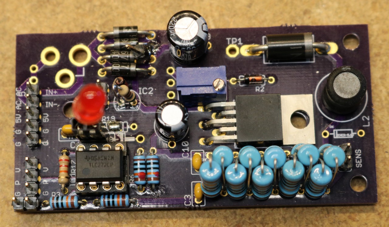
I produced a custom PCB using oshpark:
There’s a few more features on the PCB — for example I added some diodes so I can feed it directly from AC.
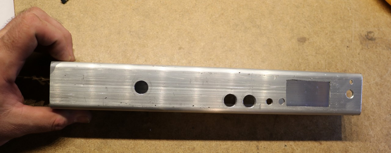
I went low-tech on making a case and just purchased some 1.75″ square tubing from the local metal supply store. It cost me twelve bucks for a 3′ piece. I only needed a foot, so I have lots of aluminum to spare for other projects.
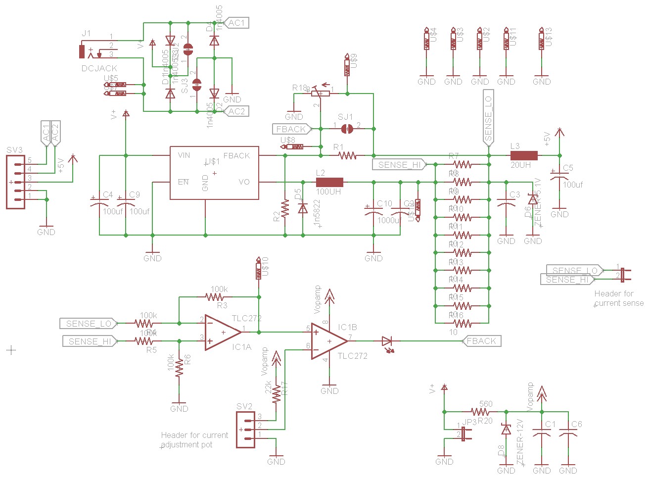
UPDATE: Several people have asked for an updated schematic, so here is one:
(make sure to click the image to see the full-size version)
I haven’t had a chance to clean up the above for publishing yet. Here’s a few important notes and corrections:
- R18 (potentiometer) and R1/R2 are two different means of setting the output voltage. I mounted a 25-turn pot for R18 and then adjusted the pot to get my 5V output voltage. Implement either R18 or R1/R2, but not both. If you want to make a variable-voltage supply, then substitute a header for R18 and use a nice external pot.
- Several places in the schematic reference “5V”. That’s the output voltage of the LM2576 and is adjusted by the R18 potentiometer.
- Sv2 is a header that connect to the current setting potentiometer.
- I believe in the video I talked about using a zener to protect the LM2576 from over-voltage on the feedback pin. I’m still not sure that’s completely necessary. In my prototype I mounted a 3V zener in the place where R2 is shown in the schematic
- Note that I used ten 10-ohm resistors instead of one 1-ohm resistor for the current sense function. It’s possible you could get by with a single 1-ohm resistor, just be sure to make sure it’s of sufficient wattage.
- In the upper-left of the schematic is a bridge rectifier circuit. It’s there so I can power the supply directly from an AC transformer. The two solder jumpers show are to allow omitting the diodes in case a DC supply is available.
- The schematic is littered with test pins. These served some purposes on the PCB, letting me put an extra pad somewhere that I wanted one, or letting me fudge a component layout such that it would fit a different-size component.
- The schematic incorporates an additional inductor (L3) together with a capacitor (C5) that reduces output ripple significantly. This was suggested by one of the youtube commenters, and is referenced in the LM2576 data sheet.
- The zener diode D6 was meant to be an overvoltage protection diode. I never implemented it on the prototype.
Hello,
I’m thinking of building a high voltage version of your LM2576 power supply. Do you have an updated schematic showing the additional 3.3 volt zener diode? Also, how do you obtain the 1 volt reference used by the current regulating potentiometer?
Thanks.
I don’t have an updated schematic handy, but the modification for the zener is pretty simple. It’s from ground to the feedback pin of the LM2576. I believe I derived the reference for the potentiometer from the same supply that feeds the op-amp. I used a 22k resistor from that supply to the pot. According to my calculations, this should have yielded a range on the pot of approximate 0 – 2V. Part of that range is wasted, as my supply is never going to get up to 2A output, but it was a reasonable simplification of the circuit from parts I had on hand.
Hi, first of all, you made a really interesting project, good video and explanation.
I want to make something like this, but im having some trouble, can you post/send some schematic with the values of all resistors/capacitors, and can you tell me what is the max current that the circuit can cut???
I would be really greatfull 🙂
Cumps and keep making the projects
thanks for the circuit, I have an LM2596 and I was searching for a circuit to limit the output current and now I found it. I would like to know, since I am in the design process, if I want to limit the current to 2.5A, does that mean if my load requires more than 2.5A, the LM2596 will shut down? if so, this can also serve as short circuit protection.
thanks again for the circuit
Hello,
do you have some updated schematic that can provide??
Im trying to build a regulated power supply, but my current regulation in not working properly, what are the potenciometer values that you used for current and voltage??
Thanks.
I have expanded your construction to build the 6-channel LED regulated current driver using six independent LMs and driven from an AVR by RC-integrated PWM signal. Will send some follow-up after my prototype start to work 🙂
Hi,
Your circuit is very helpful for me to understand about SMPS. However, there is something bugging me. How do you supply the LM2576 with rectified unregulated AC without breaking the IC? I’ve looked up the datasheet, and it says max supply voltage is 60V for the adjustable version. How do you manage that?
Hello
The maximum voltage for the feedback pin is 1.23, but you apply a lot of voltage (10 volts) by inserting the LED at the output of the amp amp.
What are the reference voltage calculations?