In this post, I turn a raspberry pi into a virtual storage device for ISA bus computers:
Motivation
I’m tired of carrying compact flash cards and/or floppies back and forth to my XT computer. I like to do development at my desk using my modern windows PC. While I can certainly use a KVM switch to interact with the retro computer from my Windows desktop, it would be a lot more convenient if I could also have a shared filesystem. There are several alternatives, from serial port solutions, to network adapters. However, I wanted something that would emulate a simple disk device, like a floppy drive, something I could even boot off of, so I implemented a virtual floppy served from a raspberry pi.
Connecting a modern Raspberry Pi to an ancient ISA computer
I wanted to come up with something that had the potential for high performance, so I thought I would try a dual-ported memory design. Dual-ported memory has the advantage that two different users can simultaneously use the memory without interfering with one another. A typical example is video cards where one user is the computer updating the video RAM where another user is the display adapter sending the contents of the video ram out to the display adapter.
Checking digikey, I found that a 1 kilobyte dual ported ram does exist, and it’s even through-hole. The device is the IDT7130. I set out to figure out how to interface the IDT7130 to both the PC’s ISA bus and the raspberry pi.
Design
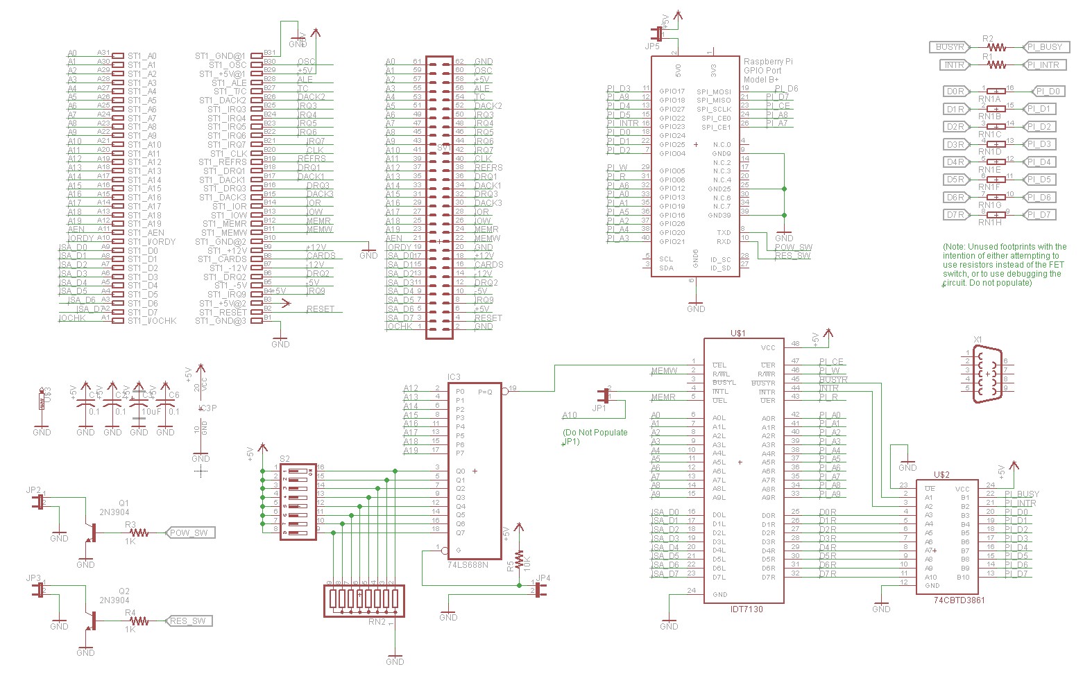
Below is a schematic:
The first task is to get the dual ported RAM onto the ISA bus. Fortunately this is relatively simple. A 74HCT688 together with dip switches and pull down resistors forms the address decoding logic and provides a chip select to the left port of the IDT7130. The ISA bus’s data pins, address pins, and control pins (MEMR, MEMW) connect in the obvious way. It’s really no different interfacing this dual ported ram than it would be to interface a static RAM.
The second task is to interface the dual ported RAM onto the raspberry pi’s GPIO. For signals that are output from the pi and input to the ram (address, control lines), this is relatively simple as the pi’s 3.3V GPIO’s high logic level is sufficient to register as a logical high on the IDT7130.
Interfacing the data bus, however, is more difficult. The data bus has to be bidirectional. Pi-to-RAM transfers wouldn’t be a problem, but RAM-to-pi transfers would lead to 5V logic levels being sent to a 3.3V raspberry pi. I measured the logical high output of the IDT7130 at approximately 4.6V. This would be high enough to damage the pi’s GPIO interface. I chose to use a 74CBTD3861 FET bus switch to remedy this, a suggestion made by a helpful member over at vcfed. The 74CBTD3861 includes a dropping diode that is suitable for interfacing 3.3V logic. This is an SMD device, which is somewhat unfortunate as I try to avoid SMD devices in my retro builds, but fortunately it is a relatively large and easy to solder package.
The other feature I wanted was the ability to have a hardware reset, for those times when the PC is so thoroughly locked up that a software CTRL-ALT-DEL is insufficient. I used a 2N3904 to provide an open collector output. Running short on GPIO pins, I used the pi’s RXD line to drive this transistor. This is fine, as this line is also a GPIO, but has the disadvantage or (or advantage depending on how you look at it) of automatically being pulled high during the pi’s boot sequence.
Implementation
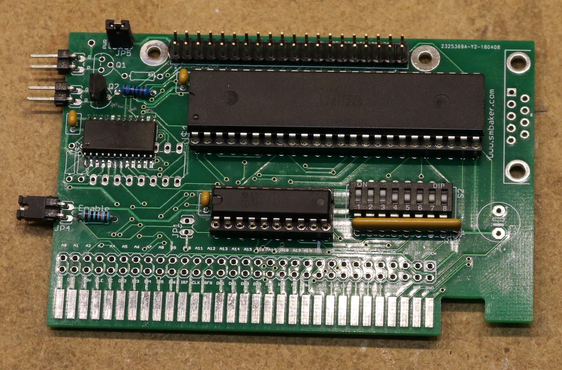
I had the pcboards made at JLCPCB:
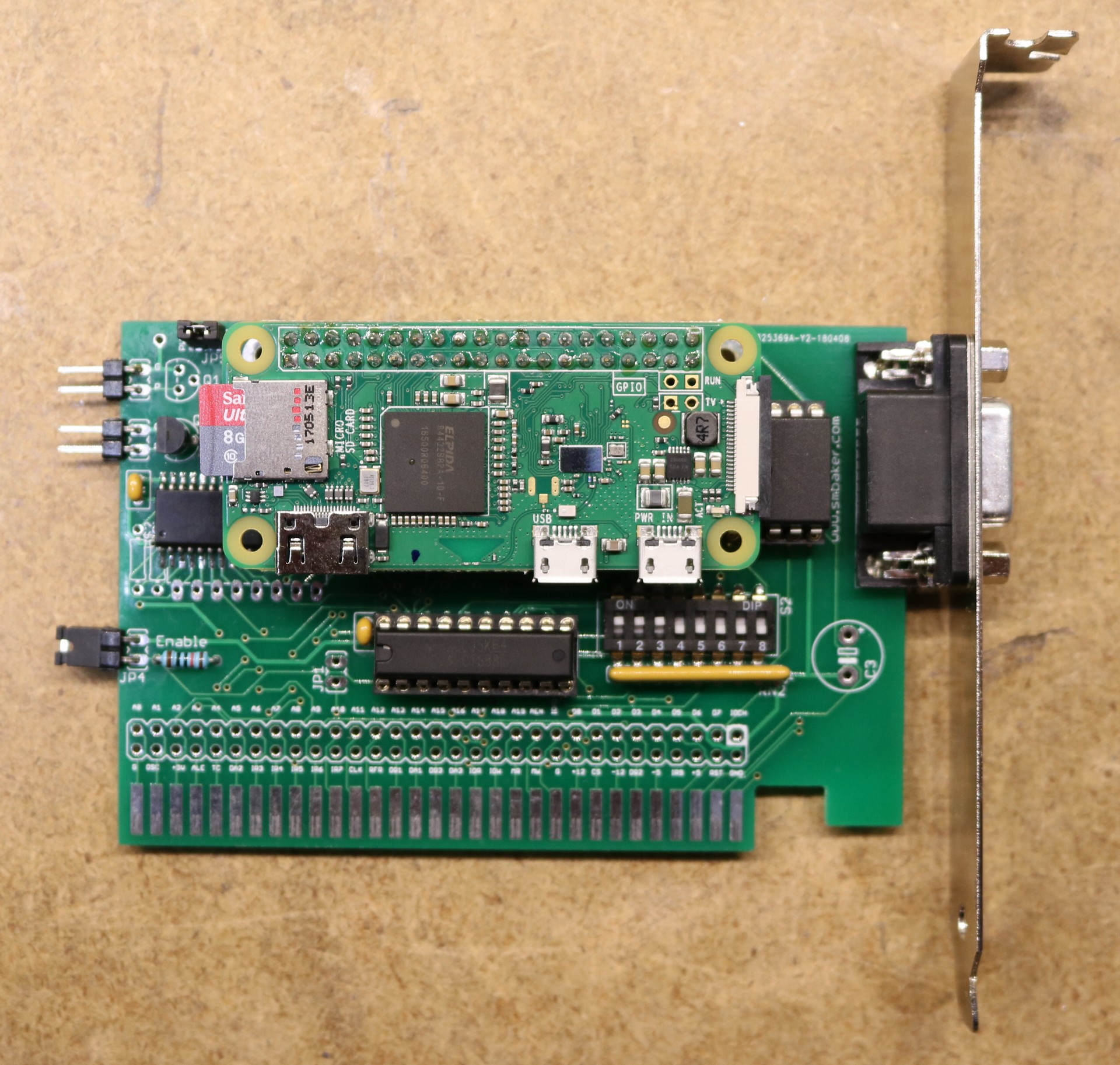
Here’s a picture with the raspberry pi mounted:
The DB9 connector is not actually connected electrically. It’s solely there to serve as a means to mount the metal bracket to the pcboard.
Software
The software is available in my github repository at https://github.com/sbelectronics/pi-isa-drive
The software consists of two pieces:
- An int 13H BIOS extension that runs on the PC
- A server that runs on the raspberry pi
Int 13h Bios Extension
Int 13h is the bios interrupt handler that is responsible for servicing floppy and hard drive IO requests. The operations are relatively straightforward (initialize controller, read sectors, write sectors, get disk parameters, etc). Normally this handler is implemented in the computer BIOS.
For this project, we replace the default BIOS handler with our own. If a request comes in for the drive that we want to emulate, then we service the request ourself. If the request is for some other drive, then we pass it to the old handler. Servicing the request ourself involves writing the request to the shared memory and waiting for the response to be fulfilled by the raspberry pi.
The BIOS extension can be implemented in two different ways. First, it can be assembled as a .COM file, like any other small DOS program. The .COM file needs to be run from the DOS command line. The .COM file does require some memory and will exit using the TSR (terminate and stay resident) DOS call. Because the .COM file needs to be run from the command line, you can’t boot from it.
Second, the BIOS extension can be installed into the dual-ported RAM. This requires stripping it down to remove some of the frills such as printing informative messages to the console. It has to be made to fit into 512 bytes of memory. This does allow the computer to boot from the BIOS extension using the virtual floppy image from the pi. Since it isn’t run from the command line, there’s no additional RAM required, and it doesn’t need to TSR.
Raspberry Pi Image Server
On the raspberry pi, we run a python program that continuously checks for new requests in the shared memory and services them. As the R_INTR pin on the dual ported RAM is connected to the pi, polling for requests is as simple as checking one GPIO to see if the interrupt has been triggered. Once a request is detected, we read the request parameters, perform the necessary operations on the floppy image, and write the response back to the dual-ported RAM.
The python server makes use of a C extension to implement memory transfers through the GPIO efficiently.
Dual-port RAM organization
The dual-port RAM is 1KB in size. We organize it into roughly the following parts:
- BIOS extension program space. If we’ve loaded the BIOS extension as a .COM program then this space is unused. If we’re loading it as a BIOS extension, then this space is where we stick the program contents of the BIOS extension.
- Sector Buffer. The sector buffer is where we transfer disk sectors between the Pi and the PC. Ideally the sector buffer would be 512 bytes, so it could hold exactly one sector. When running using a .COM file, that’s exactly what we do. When running as a BIOS extension, there isn’t enough room in the 1KB dual-port RAM to hold a 512B BIOS extension, 512B sector buffer, and the other necessary bookeeping state, so I reduced the size of the sector buffer to 256 bytes, and it takes to transfers to read/write each sector.
- Request Header. The request header is the AX/BX/CX/DX registers that were sent as part of the int 13h call.
- Response Header. The response header is the AX/BX/CX/DX registers that we want to return to the caller of the int 13h call.
- Bookeeping state. There’s some miscellaneous bookkeeping state, things like the original int 13h handler address that we repleaced.
- Left-side message box. This is used to signal the left-side port.
- Right-side message box. This is used to signal the right-side port.
The message boxes are a special feature on the dual-port RAM. There are two bytes, that if you write them, they will assert interrupts to their respective ports. I made use of the right-side interrupt so that the pi can detect a request by checking a single GPIO pin. I didn’t make use of the left-side port, as the PC is stuck waiting for the request anyway, it can simply sit there and poll for it until the request is serviced.
Performance
I wrote a benchmark in Turbo Pascal that sequentially writes 200 4KB blocks and then reads them back in. The measured performance is:
| Configuration | Write KB/s | Read KB/s |
|---|---|---|
| Physical 3.5″ 1.44MB Floppy | 11 | 12 |
| XT-cf-Lite Compactflash | 111 | 152 |
| Pi Virtual Floppy using pidrive.com | 92 | 145 |
| Pi Virtual Floppy installed as BIOS ext | 80 | 118 |
These benchmarks were performed on a 4.77 Mhz V20 system, running Sergey Kiselev’s Micro 8088 SBC.
Note that when operating as a BIOS extension, the virtual floppy has to use 256 byte transfers instead of 512 byte transfers in order to have room to fit the BIOS extension in the dual-port RAM.
A few casual observations:
- Just about anything is faster than an actual physical floppy drive. It’s easy to forget just what life was like back in the 80’s…
- Interestingly, in all three non-physical-floppy configurations, writes are significantly slower than reads. This might be understandable in the compactflash case, but I’m a little bit surprised the speed discrepancy between write and read is present when using the virtual floppy, as the pi should be making use of Linux’s page cache.
- The virtual floppy is 17% slower than compactflash ide for writes, but only about 5% slower for reads. I think this is pretty good, considering I really haven’t put much effort into optimizing the code.
- When running as a BIOS extension, the virtual floppy is a bit slower as it has to make twice as many data transfer requests to the pi.
Board ordering
This is the revision 1 board is available on OSH Park.
I do have several of the HASL prototypes that I demonstrated in the video remaining and might consider selling them off to interested parties. I’m not knowledgeable on modern ecommerce or shipping of physical products, so I haven’t decided yet how I will do this, what it would cost, or even if I will be selling boards directly.
I am working on a revision two board that I expect to incorporate a few improvements. Nothing earth shattering, just a few minor tweaks and filling out a slightly larger board size. Revision two will probably mature enough that I’ll have it made in ENIG rather than HASL.


I just wanted to thank you for the video on this project. I have followed your other projects but have a particular interest in this as I have a number of vintage 8-bit machines with a modern storage requirement.
Thank you very much for making the code available on GitHub. I will be sure to advise you of any updates/modifications I make to accommodate other platforms for you to have available.
Keep up the video documentation of your work, it is much appreciated.
Christopher Netherton
VA3NTH
I assume that this wouldn’t exactly work well with copy protected disk images as-is as it only handles BIOS calls, right?
I love this project. I used a virtually identical dual-ported 1K RAM chip (made by AMD at the time) to do my senior project in college back in 1991 – I built an ISA bus card to act as a DMX512 lighting controller, with an onboard V20 chip (NEC 8088 clone with faster integer math), timer chip, bootstrap ROM, and some static RAM. The board performed onboard real-time calculations to fade dimmers at varying speeds and do the serial output of the various lighting control levels at 30fps. I spent the first semester writing all the firmware in assembly to read commands and cue information through the RAM and to run the cues on command, and then spent the second semester writing a PC app to act as the “lighting board” for editing and running the cues. The whole thing was wirewrapped – wish I had OSHPark back then!
Now I think you can buy a DMX512 USB dongle for about 20 bucks. 🙂
Since you have the db9 on there anyway wire it up to the pi and have a serial connection to it for troubleshooting in case the wireless is not working and you dont want to open the case. I guess that would add a max3232 or something like that. But probably worth it.
Sean
Over the weekend I put together a board revision that wires up the DB9 for the reason you specified, if I’m going to have one it ought to be hooked up to something. I figure there may be instances where it would be useful to connect the pi to a serial port on the PC, and be able to communicate serially. I did end up using a max2323.
If the copy protection interacts directly with the floppy controller, then I agree, it probably wouldn’t support that form of copy protection.
What is the value of resistor pack?
Thanks for this brilliantly simple idea. I’m thinking about trying to generalize it a bit (split out the host bus interface), so it can be used with Apple II, Acorn Atom & BBC, z80/8085 cp/m SBC, 68000 SBC, etc, etc, and expand the software to provide various io devices, like floppy drive, hard disk, tape, uart, printer, network, etc. Might end up using a 2K or 4K SRAM chip to make the boot rom capability more useful.
I am looking for an isa board to do multiple things. It seems like if you were able to do this that sharing multiple services from the pie would be possible through one ISA card. For instance Networking, Ram, sending video to the pie and disk access. This would make and all in one card that gives the XT or Tandy 😀 a big boost of usability.
A huge project but worth a look. It has been done with amiga and trs 80 already, but never XT class.
Hello, thanks for your projects. I am creating many board using your PCBs. I have one comment anyway. It would be nice if you post the part list, too. With recommended components, especially resistor networks, etc. Additionally, why do you sometimes mark components as U$1, U$2 etc? Last remark. I find your idea to use DB9 connectors a nice one. But why you don’t add a strip line header to connect all the pins so that we can eventually connect a spare serial line to an existing multi I/O board that may be installed in the PC? Here, ok, you can add a Max232, as suggested by other guys, to connect the PI’s RS232 line. But on other boards, we could use the DB9 for a secon 232 line output connector wired to a multiserial board. A 10 pin strip connector would be OK. Thanks!
Is it possible to make a similar device for PCI?
This is the closest I’ve found to a project I would love to see/buy or make (outside my current time/skill). I would love to have an isa card that interfaced with a pi zero (or full sized) via the serial ttl. The host computer would be provided a hardware uart that can access the pi via terminal program. Strictly a for fun project.