I build a digital RF attenuator for the bench:
So what do I need a digital RF attenuator for? This started out with my DIY RF Generator project. I started out trying to use a plain ordinary potentiometer as my RF output control, and found that it screwed the output impedance all up. Then I bought a stepped RF attenuator on eBay, and found that it was too large to fit inside my case. Then I figured, well I’ll just build my own stepped attenuator, and I’ll make it digitally controlled, and I started researching designs for this. My original plan was to use a bunch of pi-attenuator circuits switched by relays.
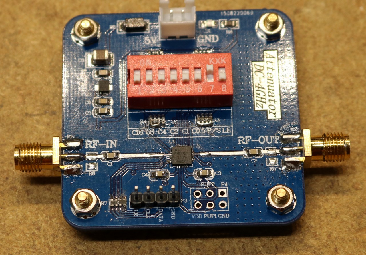
I found out that there’s an existing chip, the PE4302, that does this all electronically. It includes 6 steps, each an individual pi-attenuator circuit, and allows them to be switched into circuit. It has a simple serial protocol that can be used, basically just a clocked latch. I ordered a PE4302 breakout board from eBay:
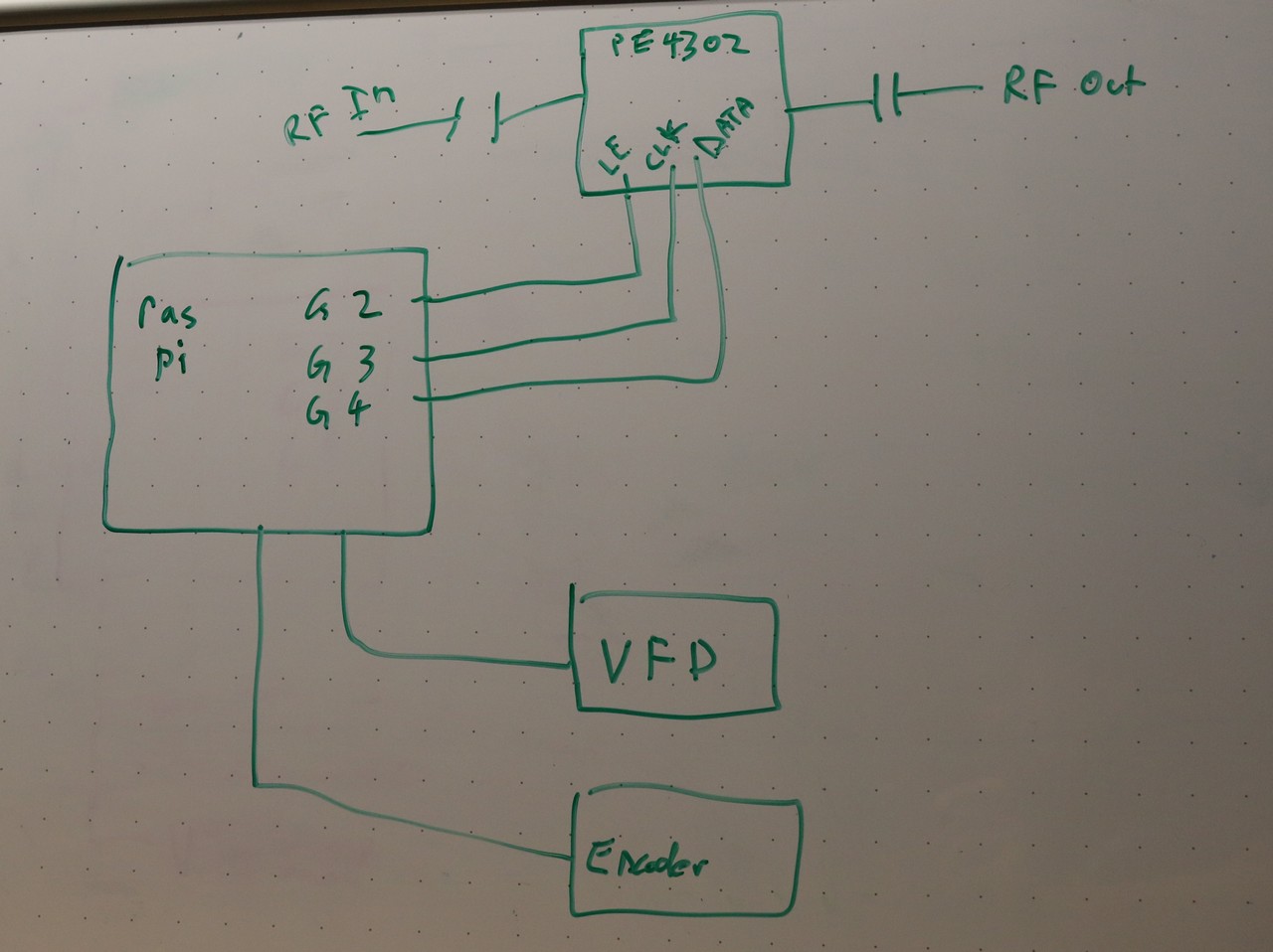
The overall project is a combination of this breakout board, together with my RGB encoder project and my VFD project:
I haven’t drawn in the connections for the VFD and Encoder; you can check other blog posts for those. The PE4302 is connected to GPIOs 2, 3, and 4. The PE4302 works just like a shift register — you clock in 6 data bits, and then you toggle a latch line to load the shift register into the attenautors output. If gives you 64 steps in 0.5dB increments, from 0 to 31.5dB of attenuation.
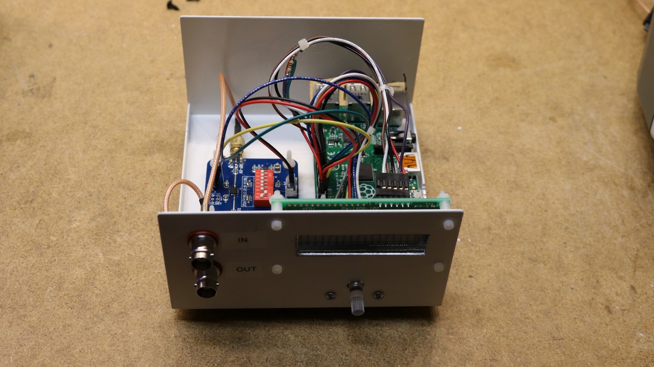
I assembled it all in a jameco instrument box and here is the result:
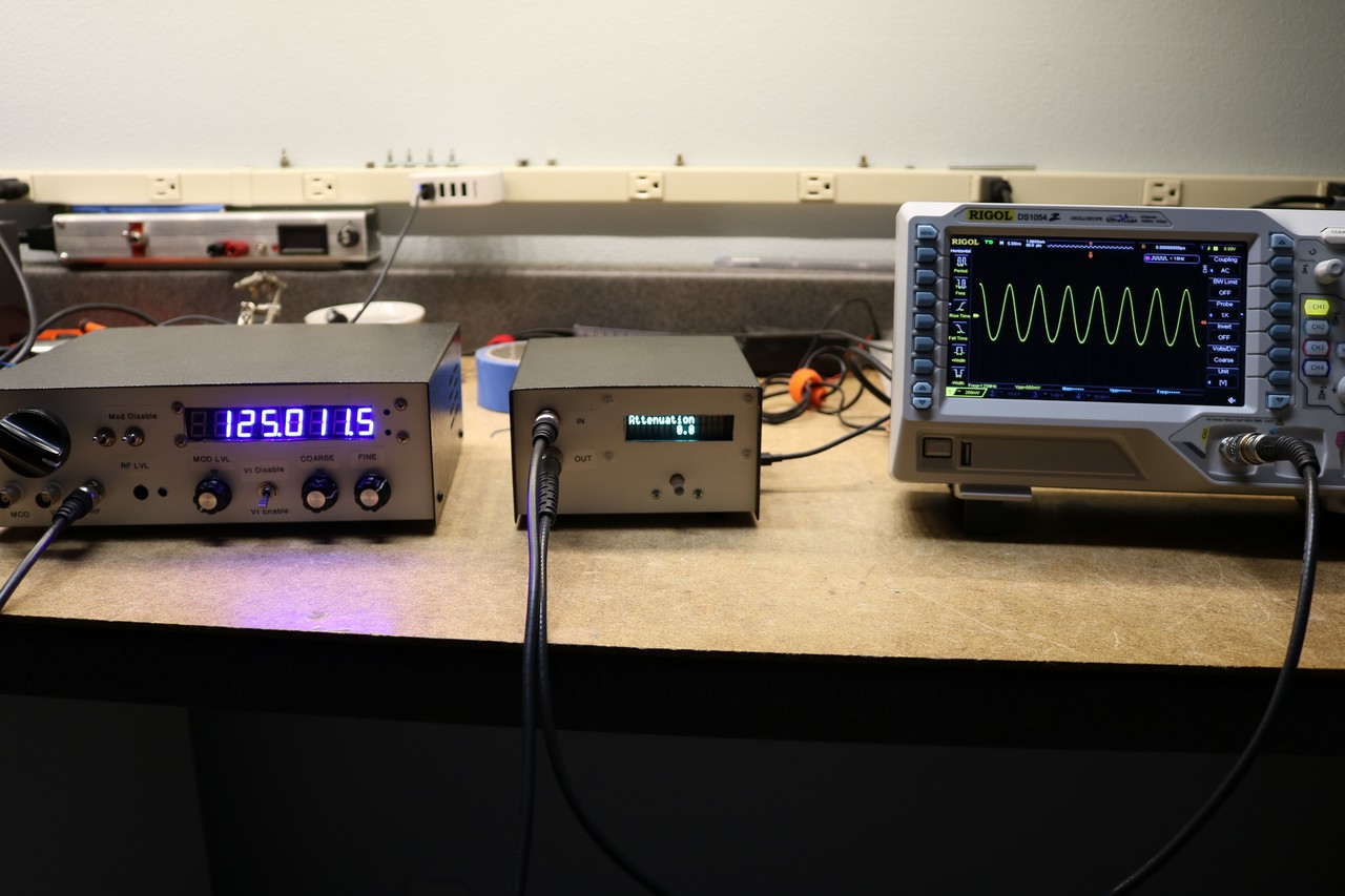
Here’s a view of the attenuator in action:
As you can see, I have it connected between my DIY RF generator and my rigol DS1054Z.
The source code is available at https://github.com/sbelectronics/pi-atten


can I buy a PCB…..is where?
tks
Hi, good job on this setup. I am in the process or building this myself, however I am using an arduino to control it all. I have my rotary encoder and lcd working and was wondering if I could have a look at your code to help me in the right direction. Thanks in advance.
Kind regards.
Hey Sheldon, you should be able to find my code in github at https://github.com/sbelectronics/pi-encoder
Hi,Thanks for sharing this. Is it possible to share your code that drives the PE4302
Thanks
Sure, I’ve just placed the code online at https://github.com/sbelectronics/pi-atten.
Scott