In the post, I build an ISA Game Control Adapter with some optional Parallel IO.
[No video yet; not sure I’m going to do one, but here’s the picture]
Motivation
My Xi 8088 homebuilt PC is running a little short on slots, so I wanted to combine the functions of a game control adapter and an 8255 PIO board. Two functions in one slot. As to why one wants each of these things:
- A game control adapter is used to interface to PC joysticks. These are the old-style analog joysticks with the 15-pin connectors.
- An 8255 board is a general purpose interfacing board, providing 24 bits of digital IO that can be configured as inputs, outputs, or a mix of both. This is not in and of itself a “parallel port”, but could probably be used to implement one.
Design
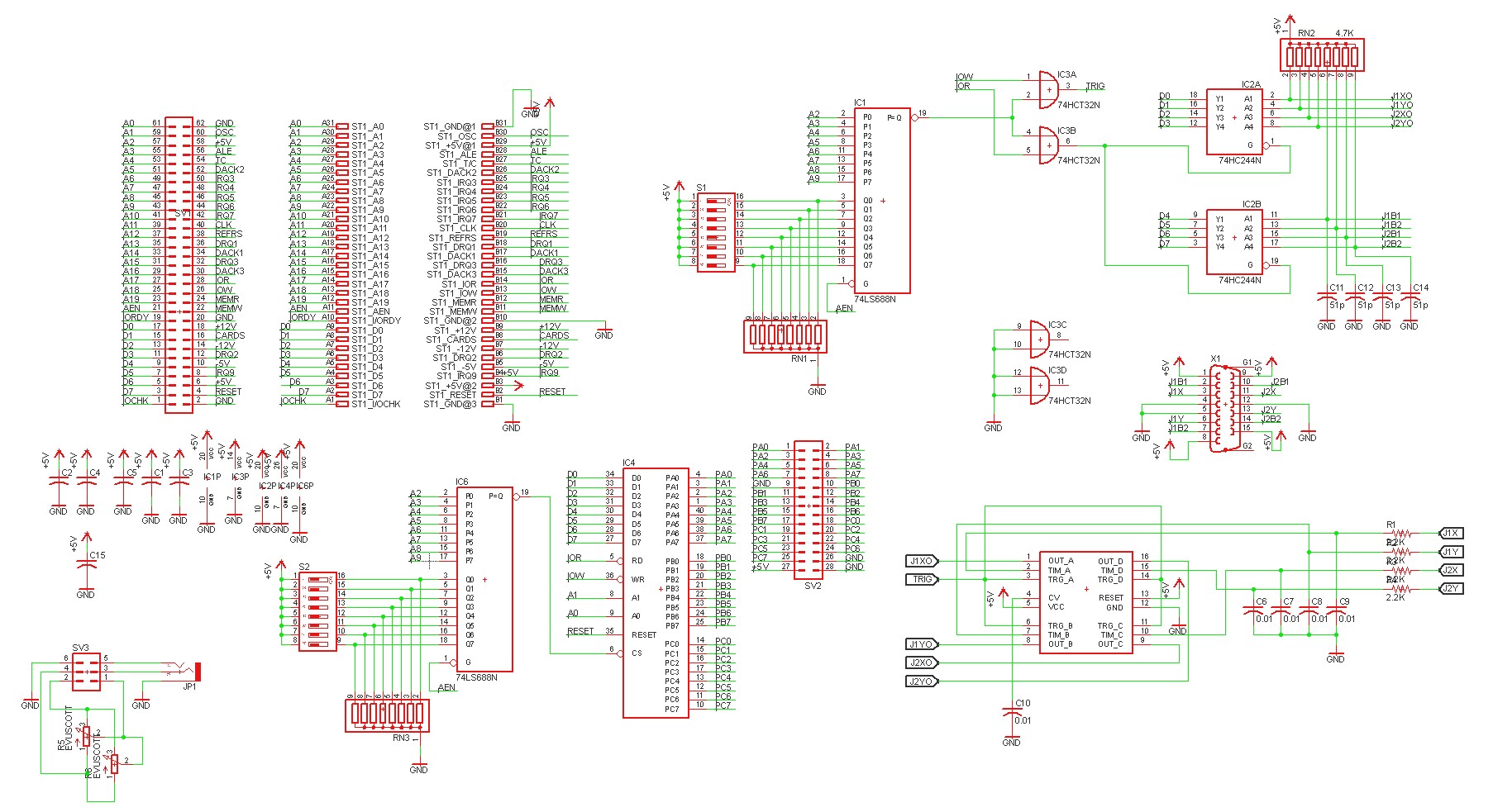
Let’s start with the overall schematic, and then I’ll dive into the the parts:
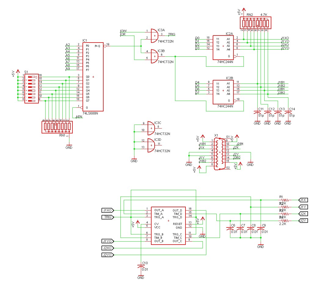
There’s a lot going on in that picture, so let’s start by looking at just the Game Control Adapter bits:
This is based on the design of the original PC game control adapter, which is documented in the PC hardware reference guide. The way a game control adapter works is by timing. The PC sends a pulse to start the timer, then the timer runs based on a resistor-capacitor combination, with the resistor being a potentiometer in the joystick. There are four axis (X and Y for joystick 1, and X and Y for joystick 2) so this normally requires four timers. In our case, we use a 558 timer. The RC of each timer is made up of an 0.01 uF capacitor and the joystick’s potentiometer plus a 2.2k resistor.
A 74LS688N and some dip switches are used to select the IO address of the GCA. This provides quite a bit of flexibility, allowing you to put the GCA on any 4-byte boundary of port address space. Perhaps more flexibility than we need, but why not… As implemented, this board will consume four addresses for the GCA, because the A0 and A1 pins are not decoded. That’s because we have 10 bits of address space, yet the 74LS688 is only 8-bits wide, so I had to sacrifice two bits somewhere.
The timers are triggered whenever the GCA port is written to, this is derived from combining the ISA IOW signal with the chip select from the 74LS688. All four timers are triggered at the same time. The timer state can be read from reading the game port, by use of a 74HCT244 buffer. At the same time you also read the state of the four buttons (two buttons per joystick).
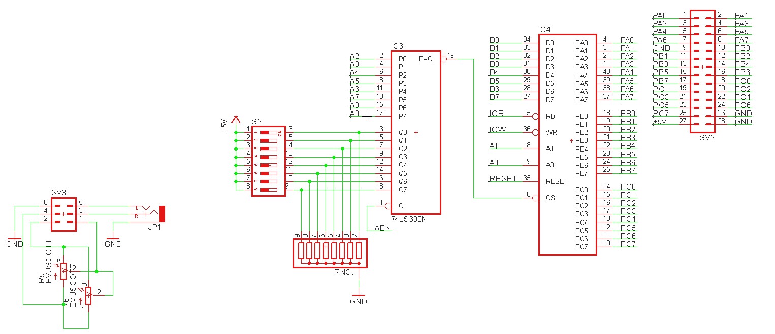
Now let’s take a look at the 8255 portion of the board:
This part is pretty simple. All the 8255 needs is some address decoding, again done with a 74LS688 and dipswitches, and it’s good to go. There’s a header that breaks out the 8255 ports so we can interface with them. On the lower left, I also included an audio out jack and a potentiometer — my plan is to eventually build a daughterboard with a DAC on it, so I can experiment with playing DAC-based music.
Implementation
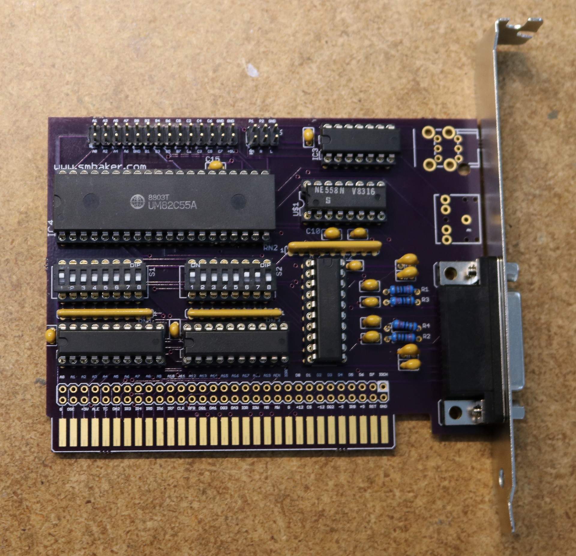
As usual, I designed the board in Eagle, routed it, and had the board fabbed at Osh Park:
Note that I haven’t populated the audio jack or potentiometer, as I haven’t build the DAC daughterboard for it yet. The big header at the bottom is something I’m including on all my ISA boards, makes it easy to attach probes to the ISA signals, and makes it practical to stack a second board on it (such as my bus terminator board), if need be.
PCB Ordering
As usual, you can find the board shared at Osh Park:


Hello Scott,
I’m a little bit confused by how you Mount the Dip Switches in all your projects. The silkscreen states the DIPSwitch can be mounted reversed as the 1 is on the right and the 8 is on the left (when watching the board in the normal orientation). But then in the pictures the dip switch is actually mounted just reversed, with the 1st dipswitch on the left and the eighth on the right. This practically reverts the functioning of the dipswitches as when the position open and close are reverted.
I’m a little bit confused. Why you never place the silkscreen in the right way?
Regards.
I kinda don’t pay attention to the silkscreen on the switches. I know I should … but I don’t. Flip them whichever direction makes sense when installing.
Hi,
is there any table for setting adresses ?
Thank you very much!