I’m going to do a series of blog posts on retrocomputing.
In this first video, I introduce the retrocomputing platform that I’m going to be using. It’s the RC2104, by Spencer, who goes by the handle Semachthemonkey on Tindie. I purchased one of his RC2104 “full monty” kits and assembled and tried it out in the video above.
Introduction
So why did I choose the RC2014 and the Z80 microprocessor for my retrocomputing projects? First, I’ve never owned a Z80, so it was an opportunity for something new. Second, I liked the design of the RC2104 backplane. It offers plenty of room for expansion, for me to design and integrate my own modules. 40-pin headers are easy to come by and easy to work with. Once you populate the backplane out with a bunch of boards for various peripherals, it makes an impressive collection of PC boards and chips.
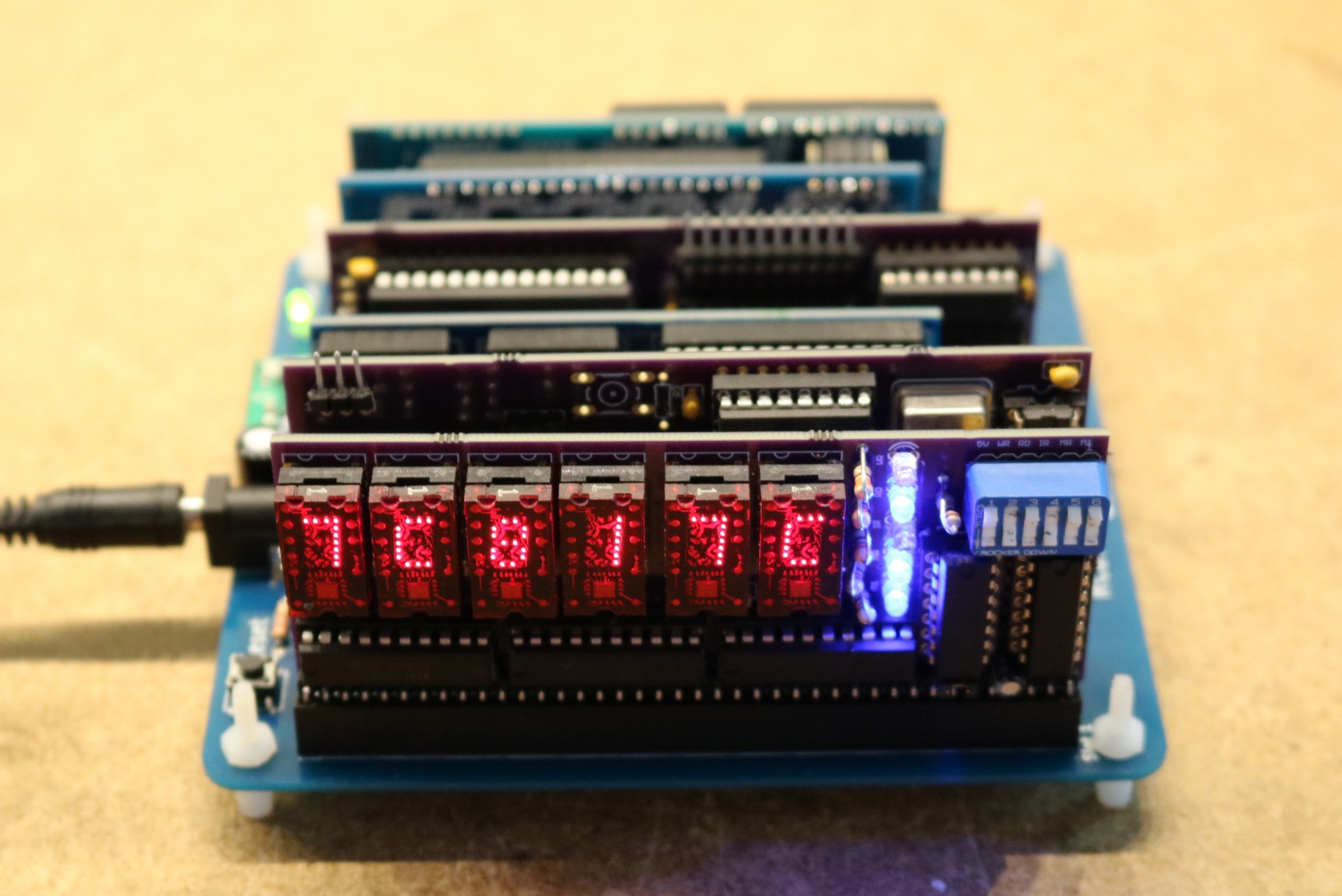
A basic RC2014 build consists of: CPU, RAM, ROM, Clock, and Serial. That’s a total of five boards on the backplane leaving room for three additional boards. In the picture above, I’ve added a bus monitoring board, a real-time clock board, and replaced the default Clock board with an I2C bus supervisor that I’m still working on. I’ll be describing the various add-on boards in subsequent blog posts.
Architecture
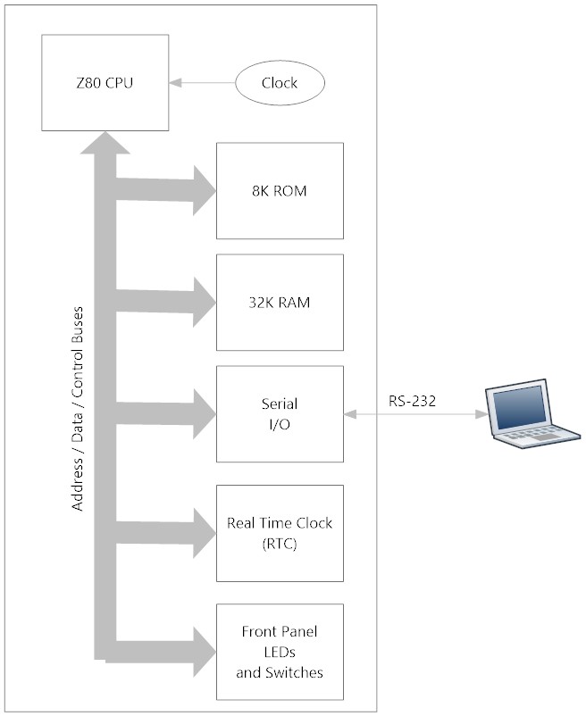
The Z80 has an Address, Data, and a control bus. The Address bus is 16 bits consisting of address pins A0-A15. The Data bus is 8 bits consisting of D0-D8. The Control bus has a number of signals, the most important ones to us when interfacing to peripherals are M1, WR, RD, IORQ, and MEMRQ.
Modules
The RC2014 Full Monty kit provided me with the standard set of modules that I needed to get the computer working. They are:
- CPU – The Z80
- ROM – 27C512 64 KB ROM, selectable in 8KB banks. This allows you to theoretically have 8 different ROMs available to boot, selectable by jumper.
- RAM – 62256 32 KB RAM
- Clock – 7.3728 Mhz crystal that drives a 74HC04 hex inverter. This clock drives both the Z80 and the UART on the serial board.
- Serial I/O – MC68B50 UART. It’s broken out to a header than can be directly connected to a FTDI cable, or you can populate the MAX232 socket for a real 9-pin serial port.
Along with the basic kit, I also purchased the Digital IO module. This consists of 8 buttons and 8 LEDs, and gives the first time retrocomputer builder something that “feels” retro.
Even before I received the kit, I had also started designing my own modules. The ones that I have built and/or am in the process include:
- Real Time Clock (RTC) and digital output – these will allow me to create a basic Nixie Tube Clock
- Bus Supervisor – By connecting some I2C I/O expanders to the bus, I hope to be able to put the Z80 into wait mode and takeover the bus using a raspberry pi. The idea is to be able to use the bus supervisor for assembly language development. I could in theory replace the ROM with another RAM chip, load programs into the RAM using the bus supervisor, and have a very rapid development cycle.
- Bus Monitor – Using some LED displays, I can show the values on the address and data buses.
- Front Panel – It’s like the Bus Monitor, but rather than using the displays to show the contents of the data and address buses, they’re addressable in the IO space so they can be set to values under program control.
- Single Stepper / Slow Stepper – Once I build the Bus Monitor, I realized the Z80 runs a little too fast for the Bus Monitor to be interesting. Slowing the Z80 down and single-stepping it will make the Bus Monitor a little more interesting.
- Speech Synthesizer – The retrocomputer needs a 1980s style voice.
- CTC Board – The CTC allows you to implement custom timers or counters. It’s a great way to generate baud rates for the serial chip.
- SIO Board – The SIO/2 is a more versatile serial chip than the 68B50, and offers two ports instead of one.
- CompactFlash Board – allows reading and writing of compactflash cards. Perfect for running CP/M on the RC2014
- Banked RAM/ROM Board – 64 KB of RAM and 16 KB (or 32 KB) of ROM. The RC2014 can boot off the ROM, and then switch to the RAM for running CP/M.
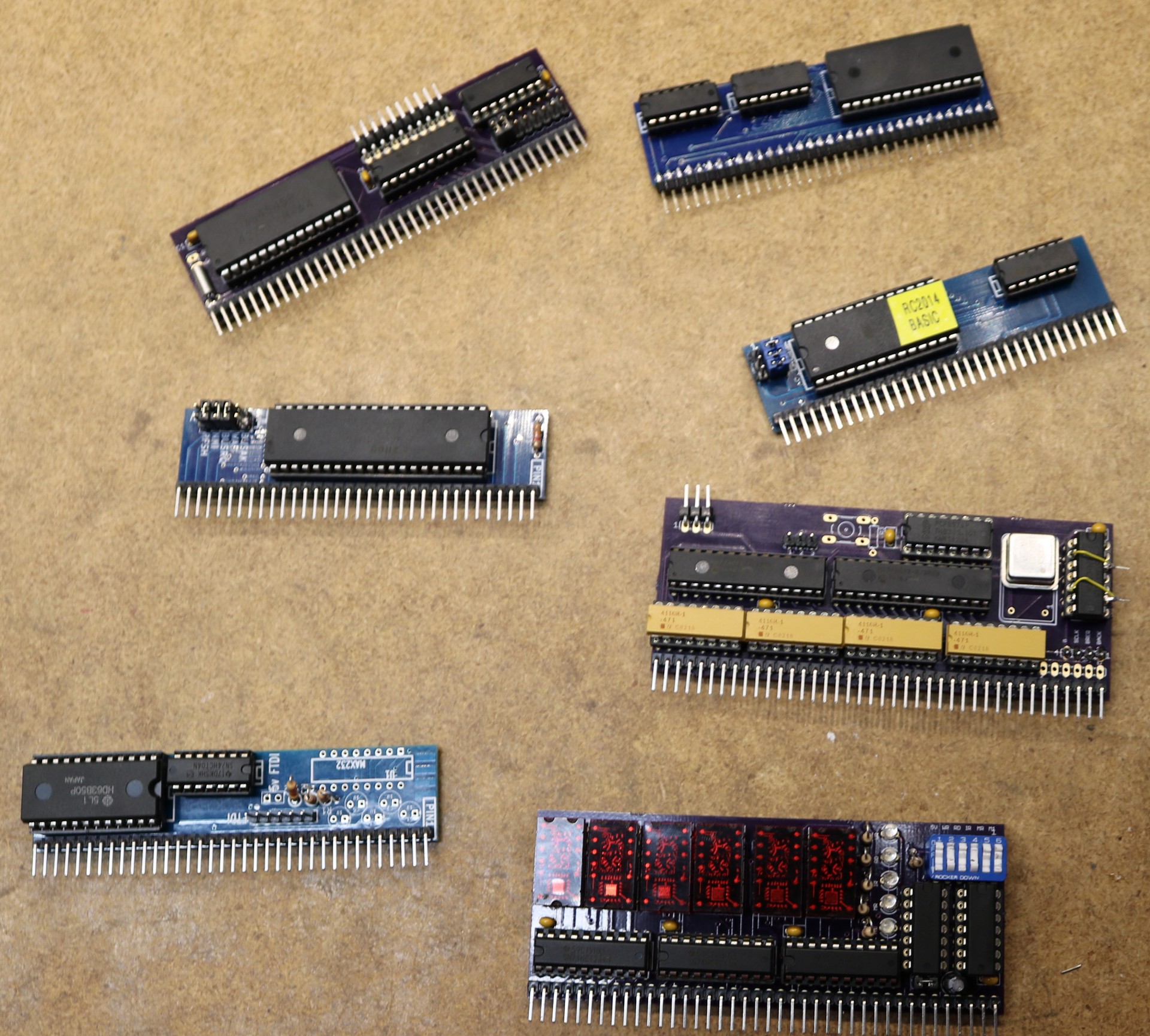
Some of these modules I’ve built already. Some I’m still developing. I’ll be placing links to the associated blog pages as things come along. Below is a picture of a pile of modules, some from the Full Monty kit, some that I built myself:
Interfacing Basics
I started this with zero knowledge of the Z80, and managed to piece together some interfacing basics by looking at the work over others. Some notable and very useful websites are http://rc2014.co.uk/ and https://z80project.wordpress.com/.
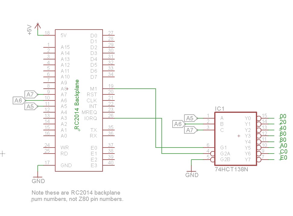
Interfacing a peripheral device generally means adding it to the Z80’s IO space. To do this there are four signals of interest to us: M1, IORQ, RD, and WR. The M1 signal is active low when the Z80 is fetching an instruction from memory or when it’s acknowledging an interrupt. IORQ is active low when an IO operating is being performed. RD and WR are active low if the operation is a read or a write, respectively. This allows us to use a 74HCT138N as a basic IO address decoder:
The upper three bits are used to select the IO addresses 00, 20, 40, 60, 80, A0, C0, or E0. That allows us to place a peripheral at any of 8 possible IO address spaces. In the above example, I didn’t do anything with the RD or WR pins. If you wanted to, you could connect RD or WR to the 74HCT138N’s G2B input, and this would cause the IO address decoder to only select the attached peripheral for reads or writes. The output of the 74HCT138N typically goes to the chip select device of the chip you’re attempting to interface to. It’s this basic IO decoder that I will end up using in most of my peripheral boards.
There are some important addresses that you should avoid, because the RC2014’s default boards use those addresses. The Serial IO board occupies addresses 80 to BF. The RC2014 Digital IO board by default occupies addresses 00 though 7F.
Logic Families
I’ve often not put a whole lot of thought into logic families — to me, if something calls for a 74xx04, I’ll use a 74LS04 just as quickly as I’ll use a 74HCT04. This Z80 retrocomputer build is the first time I’ve experienced a project where it really matters. Different logic families will place a different load demands on the Z80 microprocessor, which can only supply a few milliamps of drive to its pins. You can quickly load a Z80 down with LS parts. For my boards, I’ve been trying to exclusively use HCT parts. HCT are low power devices that still support TTL level voltages for high and low states.
You might run into a few of my blog posts or schematics where I’ve referred to a part as an HC or an LS. If so, that’s probably a mistake and I really meant to say HCT. If I do specifically choose a part that’s not an HCT then I’ll try to explain why.
Power
The RC2014 backplane can be powered by 5V, or you can add a 7805 regulator so that you can power the backplane from other voltages. I really like powering my projects from 12V, so I added a 7805.
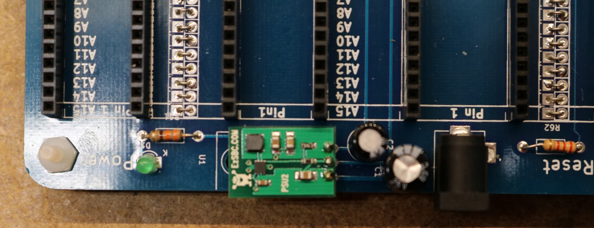
This worked pretty well until I added one of my boards that had a whole lot of LED displays, and I overloaded the 7805 regulator and it went into thermal shutdown. It burned my finger too, when I touched it. I ended up replacing the 7805 with a switching regulator made by EZSBC. These little EZSBC regulator boards are pin compatible with the 7805, more-or-less about the same form factor, and use a switching regulator. Yes, it feels like cheating to have a modern surface-mount switching regulator in my retrocomputer project, but it also eliminated burnt fingers and thermal shutdowns. Here’s a picture of the switching module mounted in place of the 7805:
Programming in BASIC
Basic was the first programming language I ever learned. It’s been a long time, but it came back to me.
I believe the particular implementation BASIC language used by the RC2014 is (either outright or derived from) this one by Grant Searle. If you’ve ever programmed any form of BASIC, then this should seem pretty familiar to you. It is handy to look over Grant Searle’s list of included keywords to know what the BASIC implementation does and does not support. While writing my simple programs, I often found myself trying to use keywords that weren’t implemented.
I found the easiest way to load and save programs is to write them up in my favorite text editor on my windows PC and “paste” them into the terminal program connected to the RC2014’s serial port. Beware that pasting a long program at 115200 baud can send data faster than the retrocomputer can keep up with it. I found it helpful to add a 35 millisecond line delay in my terminal program. The terminal program I use is SecureCRT by VanDyke technologies. It’s my go-to program for SSH, and I was happy to find that it will also talk to serial devices.
Programming in Assembly / producing custom ROMs
Sooner or later you might find you want to make a custom ROM for the RC2014. Perhaps you want to augment the Basic interpreter with some custom features. Perhaps you want a bootloader for CP/M. Maybe you just want to write an assembly language program for a custom application. Here are a few tips.
First you’re going to need an EPROM programmer. I’m using a TL866CS programmer that I bought on eBay for about fifty bucks. This is a USB-based programmer, so it should work with modern computers (beware of older programmers that use Parallel interfaces that you might not have on your modern PC). These programmers will generally program a vast number of devices. Some come with a handful of adapters for various weird SMD devices. You’ll be programming plain ordinary DIP EPROM. I’m using the TL866CS on a Windows 8.1 computer. Basically, you insert an EPROM, load a hex file using the software, and program it.
Second, you’re going to need some way to erase the EPROMs. Somewhere around here I have a UV eraser from my PIC-programming days. I haven’t bothered to dig it out yet. If time isn’t an issue, you’re supposed to be able to erase EPROMs with plain ordinary sunlight. I’ve just been tossing them on the window sill.
Third, you’re going to need the EPROMs themselves. I purchased some M27c512-12F1 and M27c512-10F1 cheap on eBay. Note that the number after the dash specifies a speed, and that may matter. I was a little concerned the -12F1 chips might not be fast enough, but they seem to be working fine.
Lastly, you’re going to need an assembler. The ROMs that Grant Searle publishes on his website include an assembled called TASM.EXE. My 64-bit Windows 8.1 system wouldn’t run it, but I was able to download a programmed called DOSBOX and run TASM.EXE inside of that. It’s a little bit tedious, so I started investigating alternatives and found a Linux assembler called zasm that I’ve been using. I find it to be faster than running TASM.EXE inside of DOSBOX. However, there was something wonky in how zasm handled hex files for assembly programs that had an origin other than zero. For example, a CP/M program with an origin at 100h or the CP/M runtime with an origin of D000h. Zasm would assemble these correctly, but output the hex file starting at offset zero. I patched the zasm source code and recompiled in order to resolve this issue.
Programming in assembly is very rewarding, as it gets you even closer to the nuts and bolts of the retrocomputer. It is, however, harder to debug. I’ve been using my bus supervisor board extensively for rapid assemble-test-revise cycles. Debugging an assembly program can be an exercise in frustration. This is one place where my TIL311 front panel or SIO/2 boards come in handy. The TIL311 front panel can be an easy way to display the occasional value by writing to a port. The SIO/2 board, with its second serial port, is handy for printing debugging info out to a console.
Scott’s github repo
My github repo containing various bits of source code and other useful things for the boards I’m working on is located at https://github.com/sbelectronics/rc2014. For example, it contains the BASIC program source for my RTC board and Nixie Tube clock.
We are working on essentially the same project….
I got a STDBUS chassis and wanted to make something interesting on it so I chose a z80 that would eventually run CP/M 3.0.
I used the same TIL311 for my front panel. I started with a breadboarded setup following “Build your own z80 computer” to understand everything and am now working on a wire wrap prototyping STDBUS card so I flesh out the system.
I plan on putting an Arduino and 32k RAM on a board as a “EEPROM Emulator” to allow the same development cycle you are working on. EEPROMS are not cheap anymore in a parallel interface, I got a FLASH but their a bit weird to program.
Laptop Computer – Dell Latitude D630
OS – Windows XP Pro with SP3
Carefully assembled and continuity tested the RC2014
cLOCK Uses 40 pin RA Header to insure correct bus alignment
32K RAM
8K ROM 13,14,15 ALL SET TO A0
Z80 CPU WAIT,BUSREQ,NMI ALL LINKED TO 5V
SERIAL I/O ADDED MAX232, R1,R2,R3, C1 THRU C5
NULL MODEM CABLE Z80 PIN 2 TO 3, 3 TO 2, 7 TO 8, 8 TO 7 & 5 TO 5
BECAUSE SCHEMATIC ONLY SHOWED Z80 PIN 2, 3, 7 & 5 CONNECTED TO MAX232
BACKPLANE PRO
RAN HYPER TERMINAL ON LAPTOP. COMM 1, 115200 baud, 8 bits, no parity, 1 stop bit, hardware handshake
There appears to be no connection although the Hyper Terminal shows it is connected.
I have thought of breaking the Null Modem cable out and looking at the RX / TX & CTS / RTS.
I suspect the Laptop setup and not the RC2014.
What do you suggest?
Tom Cochran
I built two Digital Group Z80 based computers in the 70’s and this is a fun trip back in time/
Reply to Tom Cochran,
115200 baud is way beyond the capacity of a MAX232. It is also beyond the various flavors of 1488 and 1489 parts. The RS-232 spec has max slew rate specifications. I doubt the slew rate and 12 volt levels can even be met at 115K baud. You are pushing north of a megabit/sec.
Tell Tom I worked at the Digital Group in the 70’s, and designed their dot matrix printer.