This is the fourth and final in my series of magic eye tube projects (well, unless I can find something else interesting to do with them!)
For background, please see my first magic eye tube post.
This project was heavily influenced by Mr Nixie’s Magilyzer project, which you can find here.
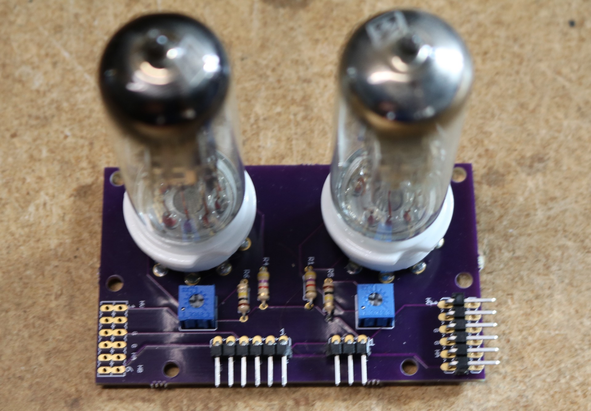
If you recall from the previous video, I had designed some two-tube magic eye tube modules, here’s a picture:
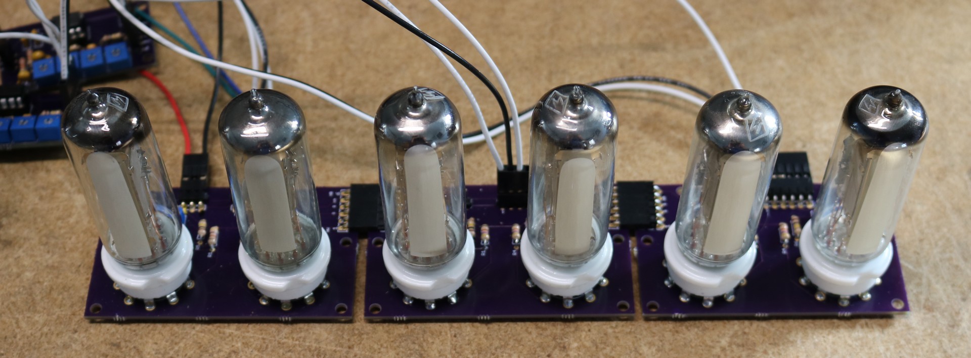
My plan was to be able to string them together into a string of six modules as so, and then connect them to the op-amp boards that I had demoed in my previous video, like so:
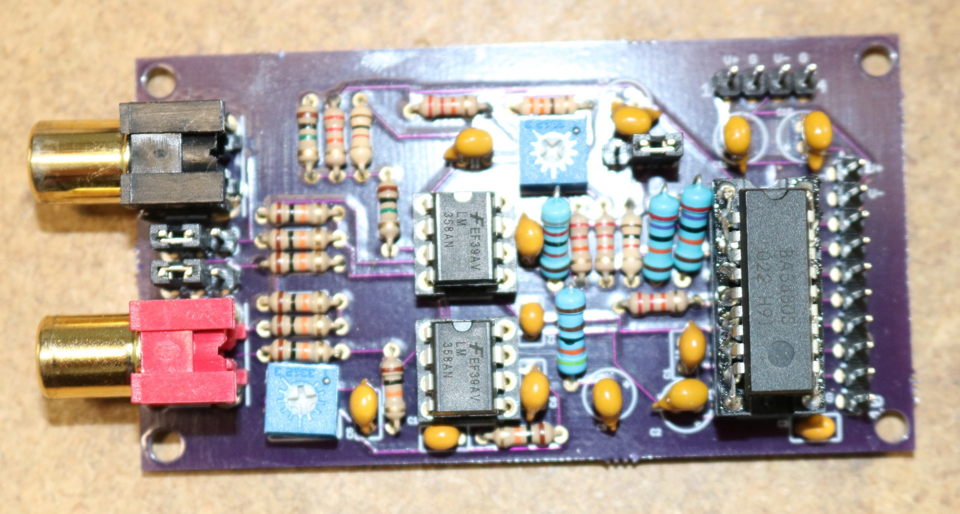
I then built a spectrum driver board, that uses the BA3830S chip. It was based heavily on the design of Mr Nixie’s design. Here’s a picture of the spectrum analyzer board:
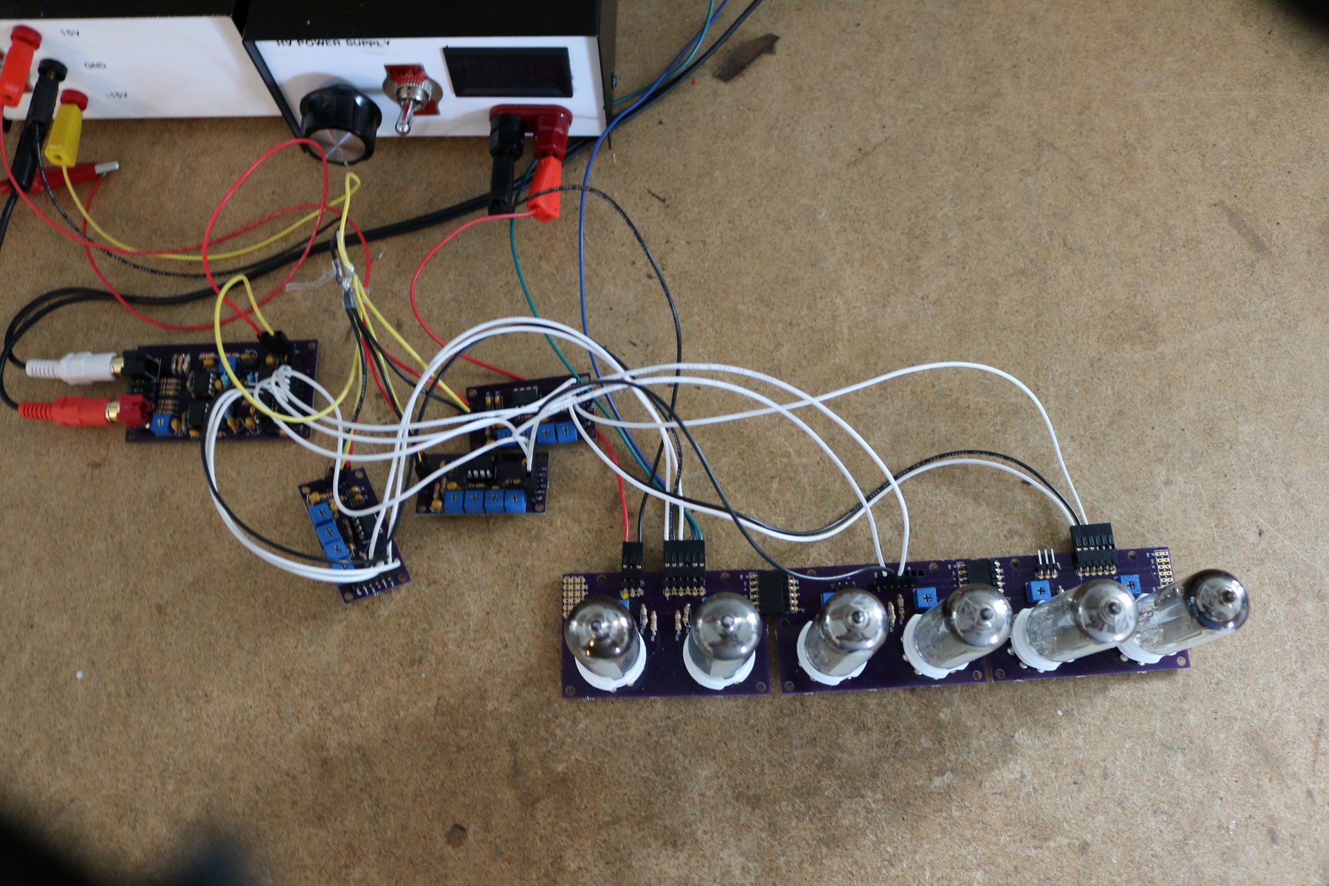
Putting it all together we have a functional spectrum analyzer, albeit somewhat of a ratsnest of wires and boards:
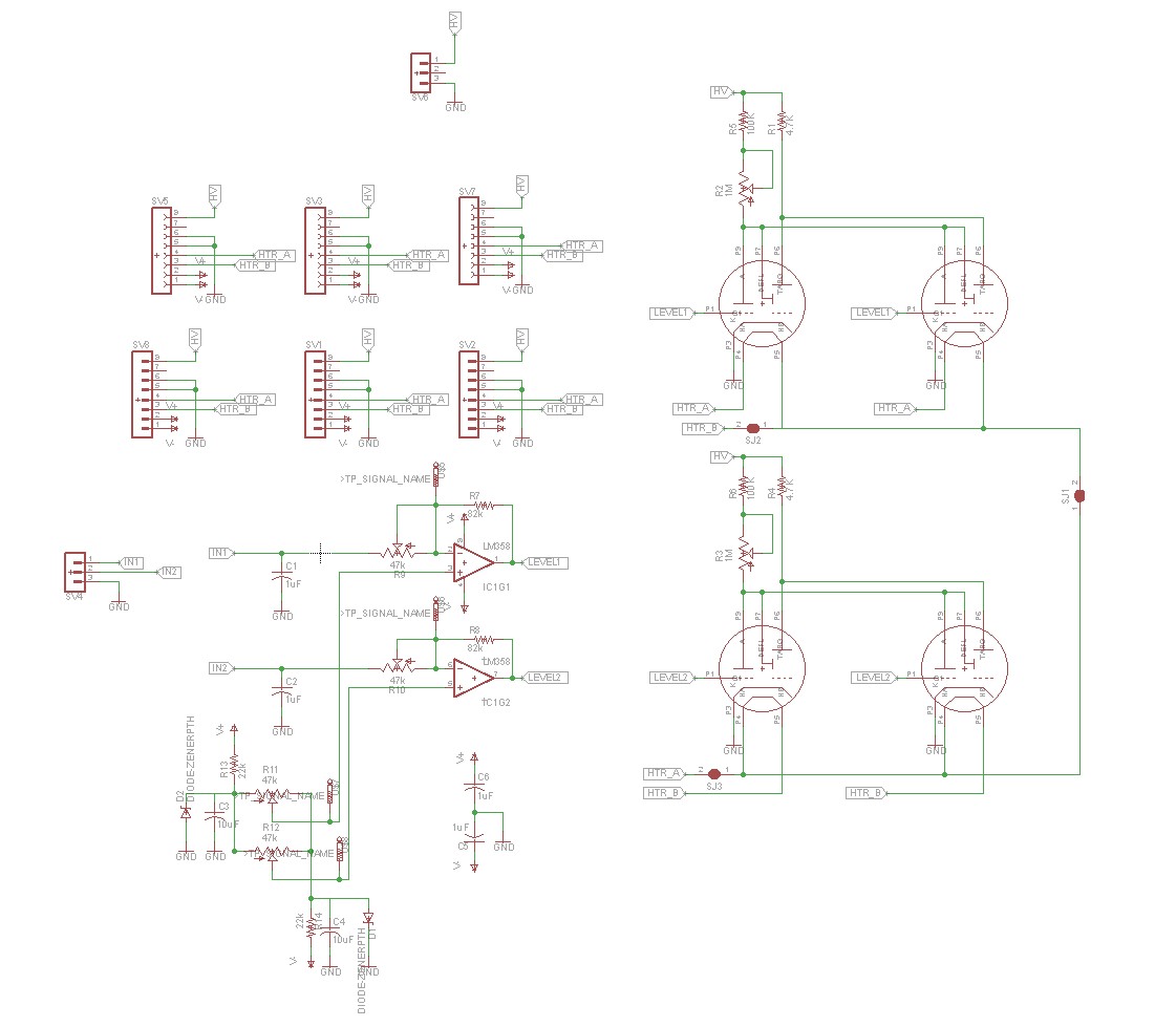
Along the way, I decided it was really cumbersome to have to deal with the op-amp boards and the wiring between the op-amp boards and the magic eye tube boards, so I redesigned the magic eye tube boards to include the op-amps. This minimizes the amount of wires and boards involved in my first prototype. Here’s the schematic of the revised dual magic eye tube board:
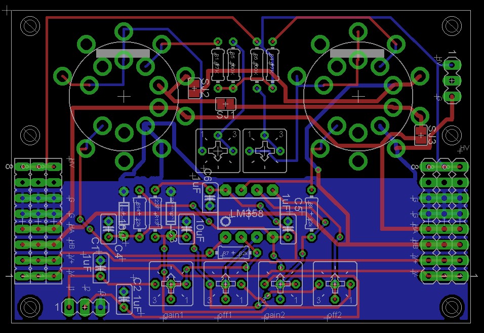
Apparently, I forgot to take out the camera that weekend, as I never took a picture of the new modules. I can show a photo of the board layout though:
The schematic may confuse some folks why it looks like there’s two sets of magic eye tubes. The reason is because I put two footprints for each tube on the board. One footprint fits the nice ceramic magic eye tubes that you can buy on ebay. The other footprint fits pin sockets (Typically called “Mouser Pins”) that you can buy from Mouser. My original plan was to use the Mouser Pins, but it turned out that the ceramic sockets are really convenient. As you can see in the above board, there’s room for the opamp, the gain and offset controls, etc. Each board is designed so that it can be daisy chained to the next, and there’s a three pin header that allows you to control the tubes (one signal pin per tube, plus a ground)
After this, I designed yet another layout for my high voltage power supply that matched the size of the driver boards. Then I stuffed it all in to an acrylic case.
[TODO: Add Picture of the Completed Project]
I bought the tube kit on ebay (em84) but when i put to my amplifier the kit doesn’t work. I had check the volt out (only 0.2 -1.5volt). Can you teach me or sell the main board can be connect with my amplifier and tube kit. I would like to buy the main can be connect with 5-6 tube. please reply to me. My mail is dungthaing2002@yahoo.com
Best regards !!!
Can you please share your schematic of the Spectrum analyzer driver board?