This blog post has two videos. In the first one, I bought a magic eye tube kit from eBay for about eight bucks, and I try it out:
In the second video, I use an op-amp that allows me to convert a positive control signal (such as output from a DAC) to the negative grid control voltage (0 to -15 V) needed to control the tube, and then I interface it to a DAC and a raspberry pi:
Basics
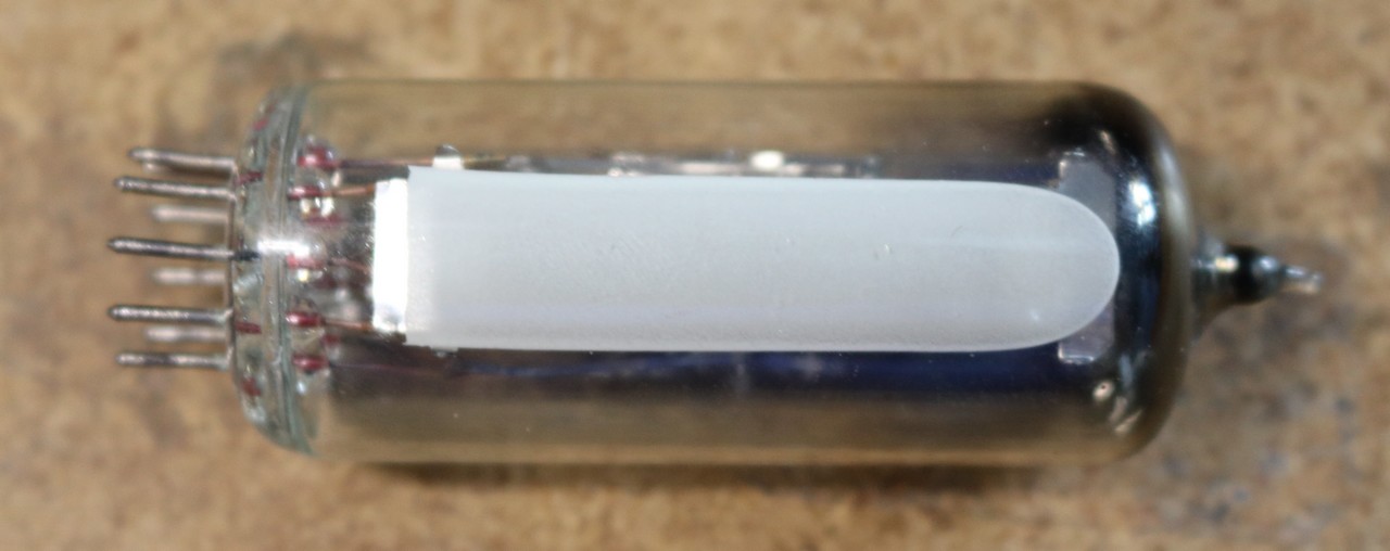
Let’s start with some basics on Magic Eye Tubes. Magic Eye Tubes are vacuum tubes, and you’ll find that they usually (if not always) require a high voltage to drive them. In my case, I’m using EM87 tubes, also known as 6E2, which work best with a 250V supply. These tubes are very plentiful and cheap on eBay. So you’ll need to break out your high voltage supply to start to work on these projects. Please be careful and use appropriate caution around high voltage. The voltages used by these tubes can be dangerous.
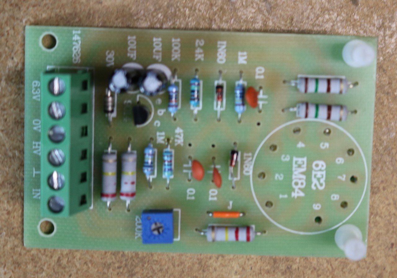
While I already knew enough about the tubes to construct my own driver, I saw that there were some kits on eBay that cost little more than the tube itself, and include the socket and some electronics. So I bought myself three of these kits. These kits implement a simple audio vu meter functionality. They don’t come with a high-voltage supply, so you’ll have to bring your own. Here’s what it looks like unassembled:
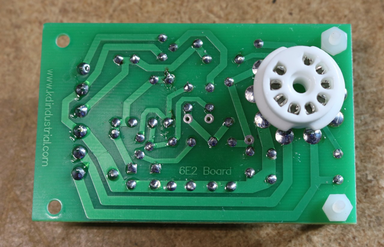
and here’s what it looks like assembled:
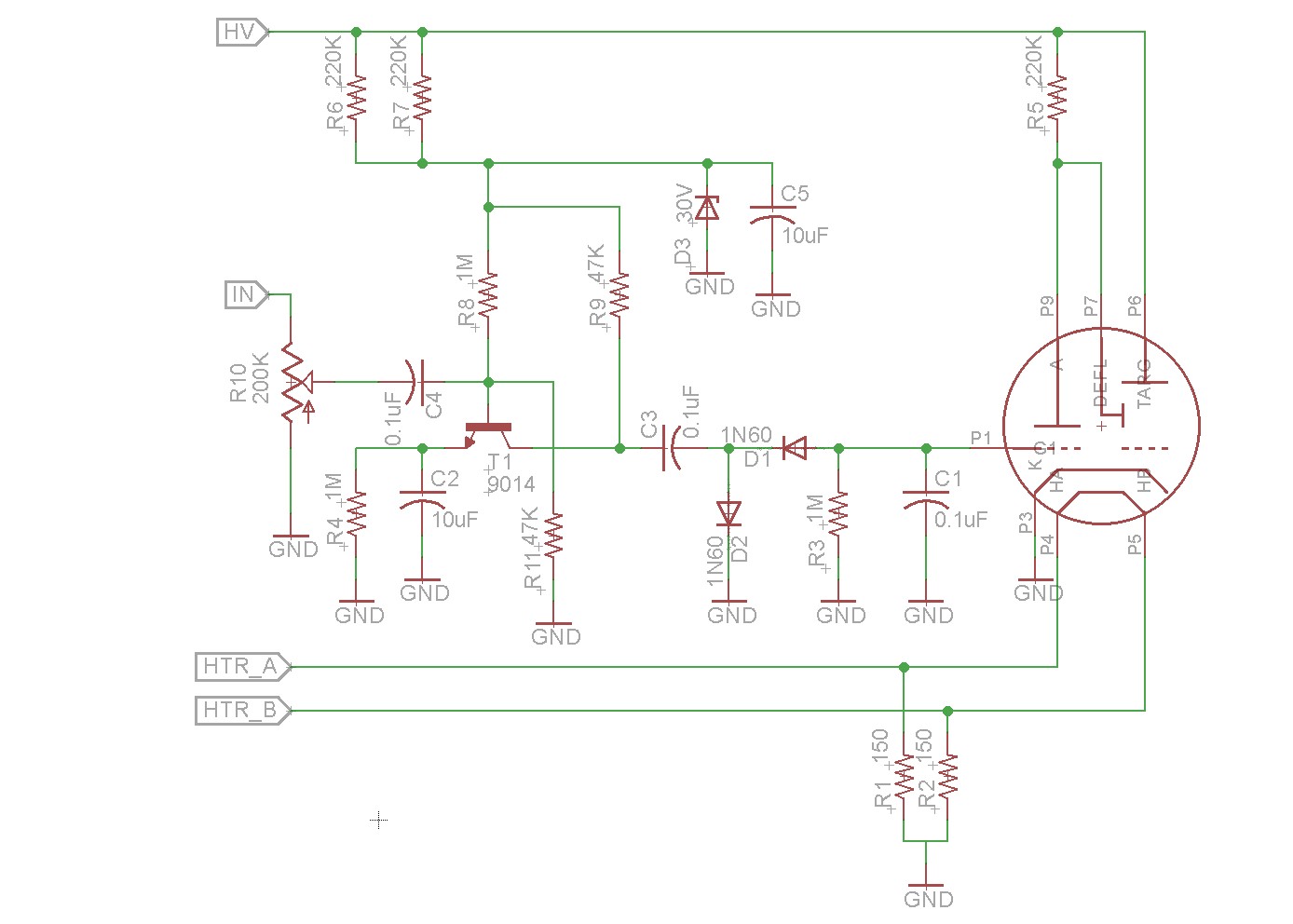
I reverse engineered the eBay board and derived a schematic from it:
Replacing the driver with an Op-Amp
I had some projects in mind, and I knew that I wanted to be able to drive the tube with positive low-voltage signals, for example from a microprocessor-controlled digital to analog converter. I also knew (from reading as well as from experimentation) that I would need to supply a negative voltage signal, from 0 to -15 volts, to control the magic eye tube. This is a perfect opportunity for an inverting op-amp circuit. I’m not going to go into detail to cover op-amps here — I recommend one of Dave’s excellent tutorials at eevblog for that.
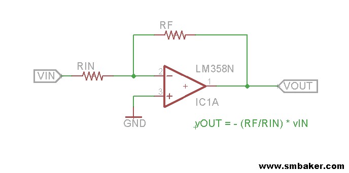
The key thing about an op-amp is that it always tries to make both of its inputs the same and it will adjust its output to accomplish that. It’ll drive its output up or down, all the way to the rails if necessary. This leads to the our basic inverting op-amp schematic and formula:
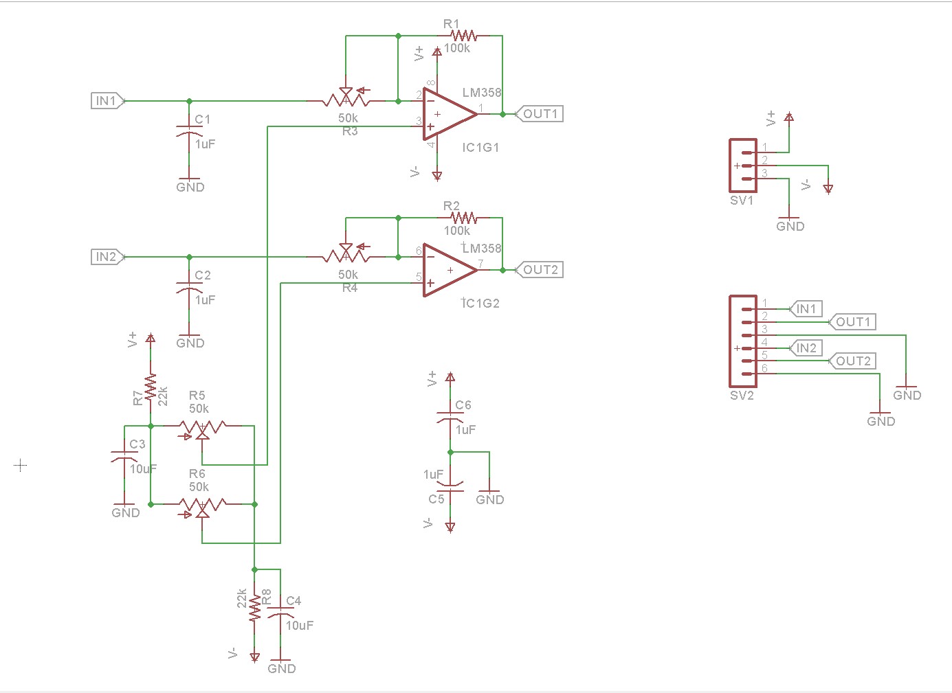
All we have to do is to compute the right value for RF and RIN, and we could turn a 0-2V control signal into 0 to negative 15 volts. Since you get two op-amps per LM358, I put together a basic op-amp driver board:
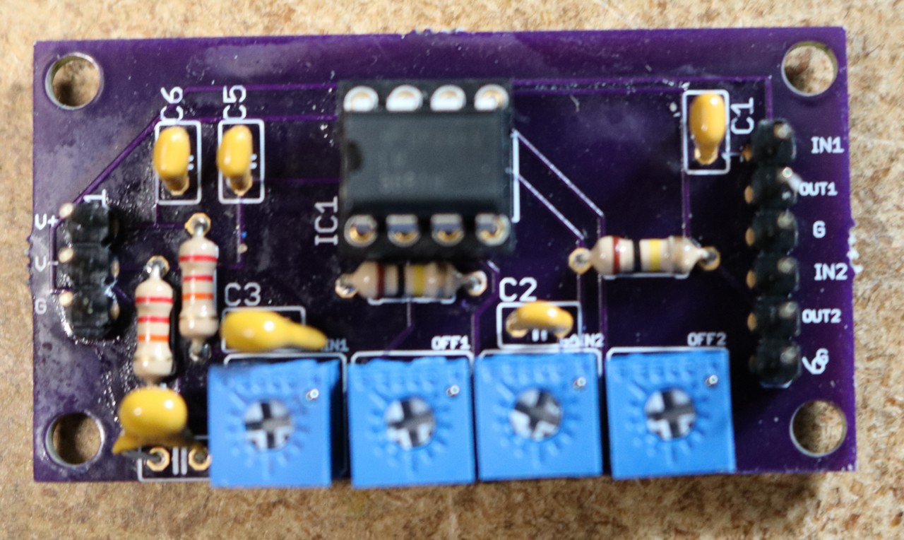
This is an extension of the basic inverting op-amp circuit. Instead of a fixed RIN, a potentiometer has been added. Instead of a fixed value to the + input of the op-amp, a variable source has been provided to control offset (remember, the op-amp will always try to make its two inputs equal, so if we offset one of the inputs, then it’ll offset the output). I have to credit Mr. Nixie at nixiekits.eu for his Magilyzer project, which was very handy to me in selecting the component values for this op-amp board. My completed board is shown below:
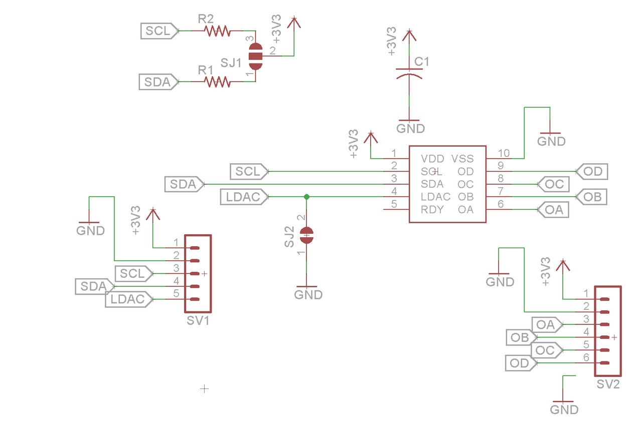
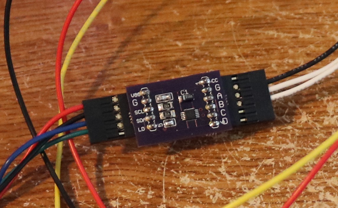
The next step to controlling this with a raspberry pi was to add a digital to analog converter. Fortunately, I had some breakout boards leftover from a previous project:
The completed board:
Wiring this up to the raspberry pi is very simple — the SCL and SDA pins connect to the raspberry pi’s SCL and SDA pins (I2C interface). The Vcc and GND connect to the raspberry pi’s +5V and ground. The MCP4728 provides four outputs. We only need one of them to drive the op-amp board and control our magic eye tube.
Great tutorial! As an old man learning electronics, I’m easily challenged. Even so, I was able to follow and duplicate your control circuits. I have a question though. Would I be able to replace spi/dac setup with a high frequency pwm signal from an arduino?