Tired of buying cartridges for my 5200, I decided to make myself a Multi-ROM Cartridge:
Purpose
The Atari 5200 is a vintage gaming system from the early 1980s. At the time I owned a 2600, but I always wanted a 5200. Well, in 2018 I finally decided to find one on eBay and buy it. I learned that the first thing you want to do after attaining a new gaming console is to get your hands on every available game cartridge for it, so I made this multi-ROM cartridge.
A multi-ROM cartridge, or “MultiCart” is a cartridge that contains more than one ROM image. There are multiple ways to go about this from selector switches to pick the cartridge you want, to built-in in game menu systems. I decided to go the route of using a Raspberry Pi for the user interface, making a WEB UI available to pick which cartridge is used.
The goal is not simply to play retro games on modern hardware — there’s any number of emulation solutions for that. The goal is to play retro games on retro hardware, but use a modern system to load the game image into the console.
Design
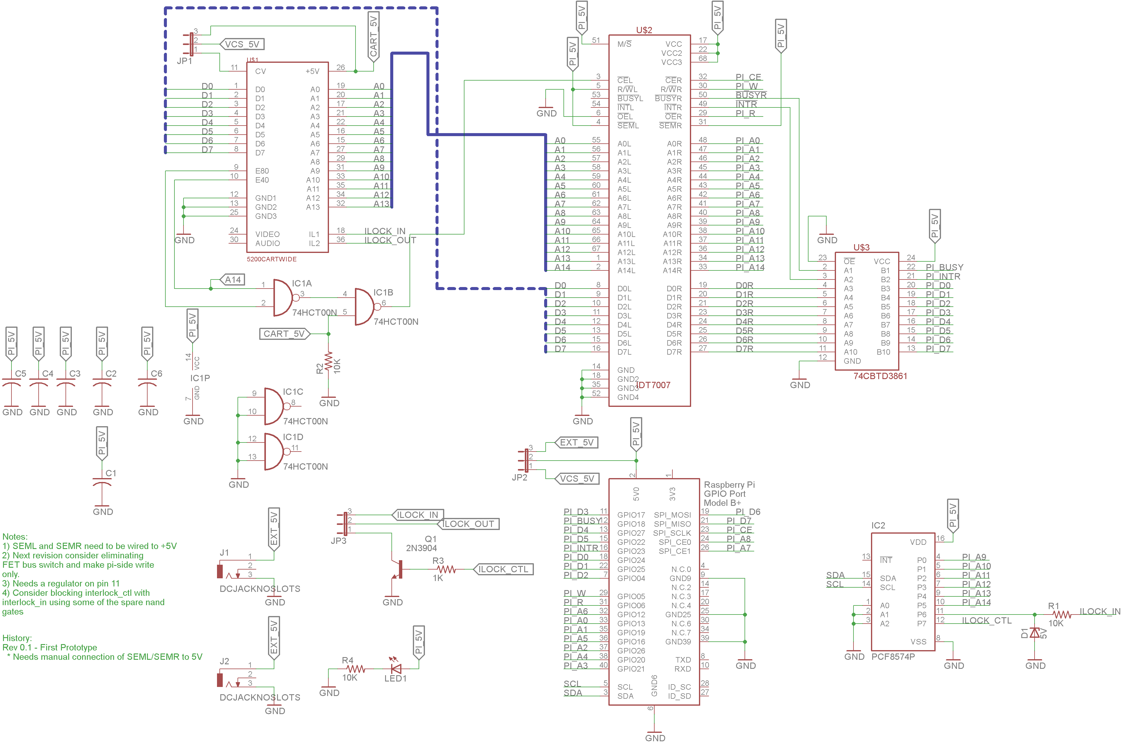
The design is similar in theme to my pi-based ISA Virtual Floppy project. In that project, I used a 2KB dual-port memory to share RAM between a raspberry pi and an 8-bit PC-XT computer. In this project, I use a 32KB dual-port memory to share RAM between a raspberry pi and an Atari 5200. The schematic is below:
Note: Do not jumper pins 1-2 of JP1. On a 2-port 5200, you would end up sending +12V into the pi, dual-port RAM, and possibly back into the 5200.
The major component to this is the IDT7007 Dual-Port memory. You can find this on ebay for $12-$15 used, or you can find it at Mouser for about $45 new. The IDT7007 has a left-side bus and a right-side bus. Both buses can be used independently — for example the left side can be reading memory while the right side is writing memory. In this project, I connected the left-side bus to the Atari 5200 and the right-side bus to the raspberry pi.
The left side is pretty straightforward, with address and data pins connecting directly to the 5200. The chip select requires some logic to combine the Atari 5200’s upper and lower chip selects. Note that the lower chip select also serves as pin A14 to the shared RAM. I’ve also incorporated into the chip select logic an input from the cartridge connector 5V. This is because I designed the cartridge (pi, ram, etc) so it can be powered independently from the Atari 5200. Incorporating the cartridge 5V into the chip select allows me to make sure that the left-side doesn’t receive spurious chip selects from an unpowered Atari 5200.
The right-side bus is a little more complicated. It supports both read and write capability, basically the same idea as my ISA virtual floppy project. Because it supports read capability, it needs a FET bus switch to do the logic conversion from the dual-port RAM’s 5V logic to the pi’s 3.3V logic. Conversion in the opposite direction is not an issue (the dual-port RAM will happily accept 3.3V logic signals), but sending 5V logic signals to the pi could be disastrous. Technically, we don’t need read capability, so the FET bus switch could have been left out of the design. I may do so in a future revision in the interest of simplicity.
I ran out of GPIO pins on the pi, and had to use an external PCF8574 io expander to drive the right-side bus’s upper 6 address lines. The PCF8574 also handles interaction with the cartridge interlock.
The interlock is how the Atari 5200 knows a cartridge is inserted. Generally a cartridge connects pins 18 and 36 of the cartridge connector together. This activates one of the 5200s power regulator circuits and allows the console to start executing code. Breaking the interlock is one way to force the Atari 5200 to reset. For this reason, I implemented an interlock monitor to one input on the PCF8574 and an interlock control to the remaining output on the PCF8574. This allows me to detect when the Atari 5200 is powered up, and to simulate the insertion and removal of cartridges.
The remaining wrinkle is power. Because we want to assume control of the interlock, we can’t use pin 26 of the cartridge connector for +5V as breaking the interlock will cause interruption of power, which would in turn power-down our pi. A potential alternative is pin 11 on the cartridge connector, which supplies unregulated DC for the VCS adapter. One would need to add voltage regulation in order to use that (something I did not know for the first board revision). The leaves the only reasonable alternative, using an external +5V power supply for the cartridge. There’s a footprint for a barrel jack on the board.
Implementation
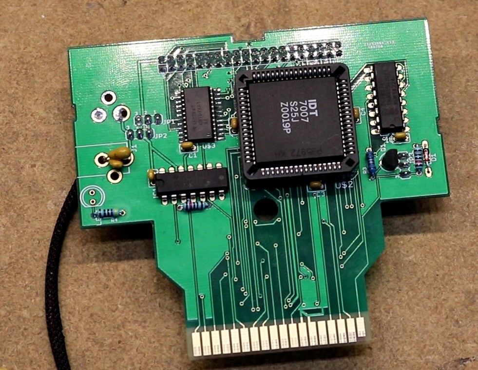
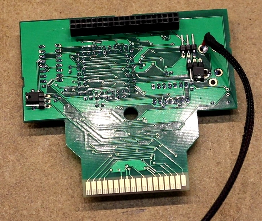
Here are the boards that I had produced:
Note that if you’re using the 0.1 revision board (Nobody but me is using it at the moment!) then you must manually connect SEML and SEMR to 5V
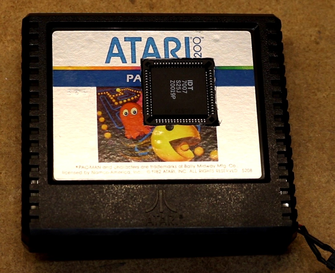
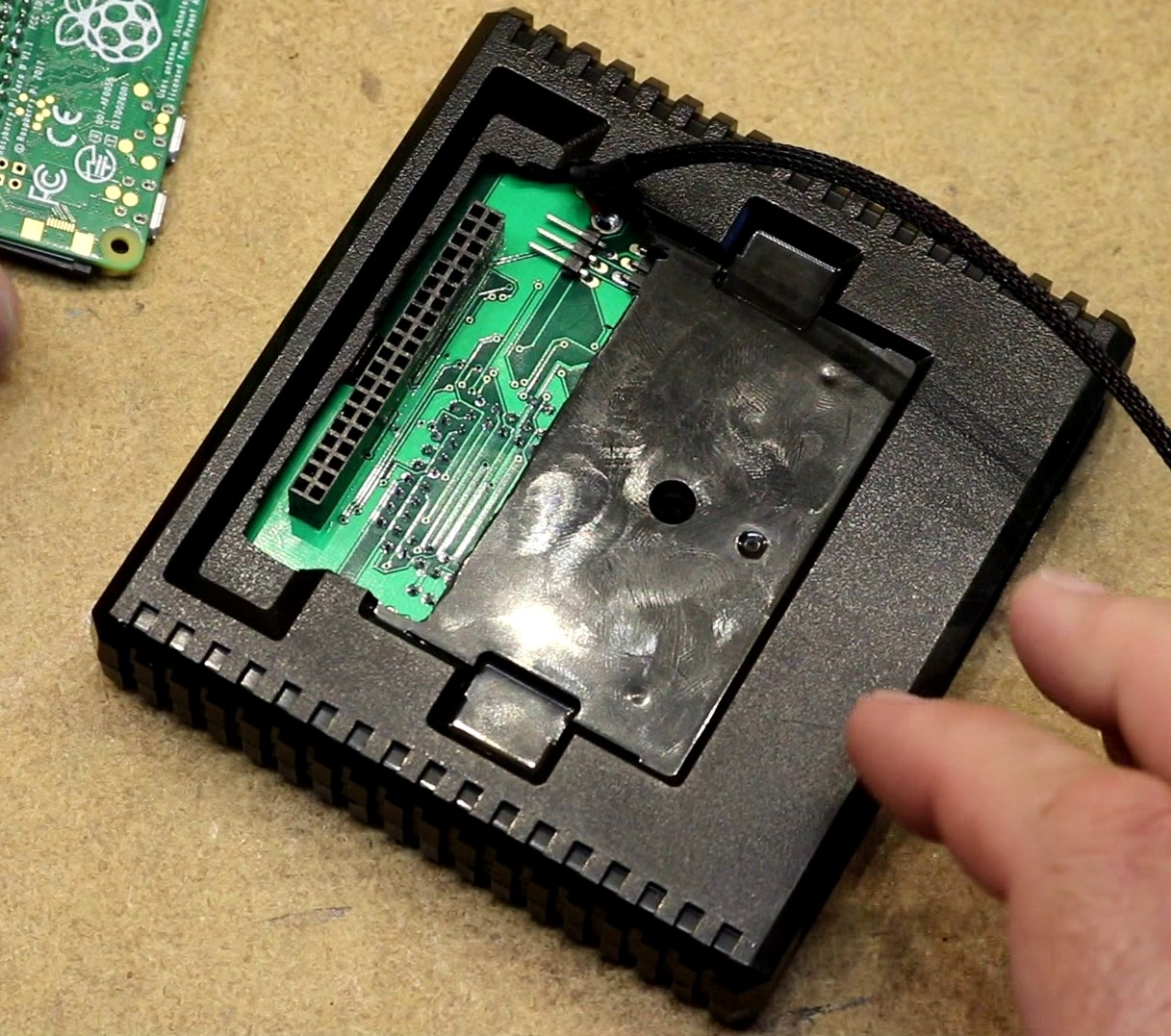
Both the dual port RAM and the Pi Zero W are too big to fit inside of an Atari 5200 Cartridge. I ended up having to make cutouts in both the front and back of the cartridge. Here are some images of the cartridge surgery that I performed:
Software
The software is available for download on github:
- smb-pi-lib: https://github.com/sbelectronics/smb-pi-lib
- pi-atari: https://github.com/sbelectronics/pi-atari
Comments (1)