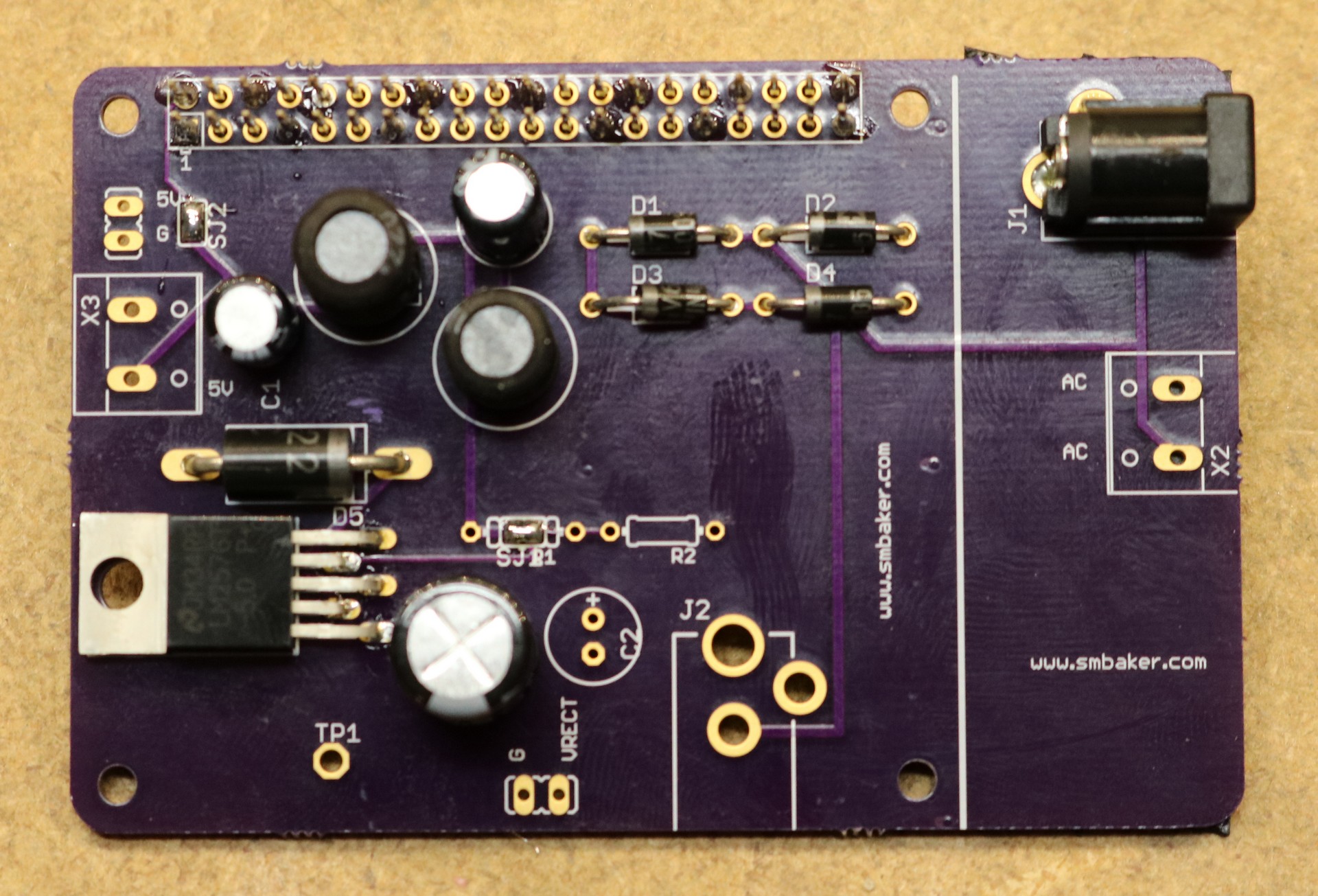
I like to power my projects from 12V, and the Raspberry Pi only natively supports 5V. Often I’ll add a small switching power supply to my designs to accommodate this. I finally got around to making a supply in the form factor of a shield (I’d call it a “hat”, but technically I believe a “hat” requires a configuration eeprom). Here’s the result:
As you can see, I’ve designed it so that the power jack can be placed in either of two locations, one of them right on top of the ethernet and USB ports, which happens to correspond with the back panel location of many of my projects. I’ve also made provisions for terminal block power input. There’s a full-wave bridge rectifier, so it can be plugged into AC. There’s an output header for 5V out as well as a terminal block for 5V out, so it can be used to power external electronics as well. The white line shows where the board can be cut, to discard the portion that overlaps the USB and Ethernet ports, if desired.
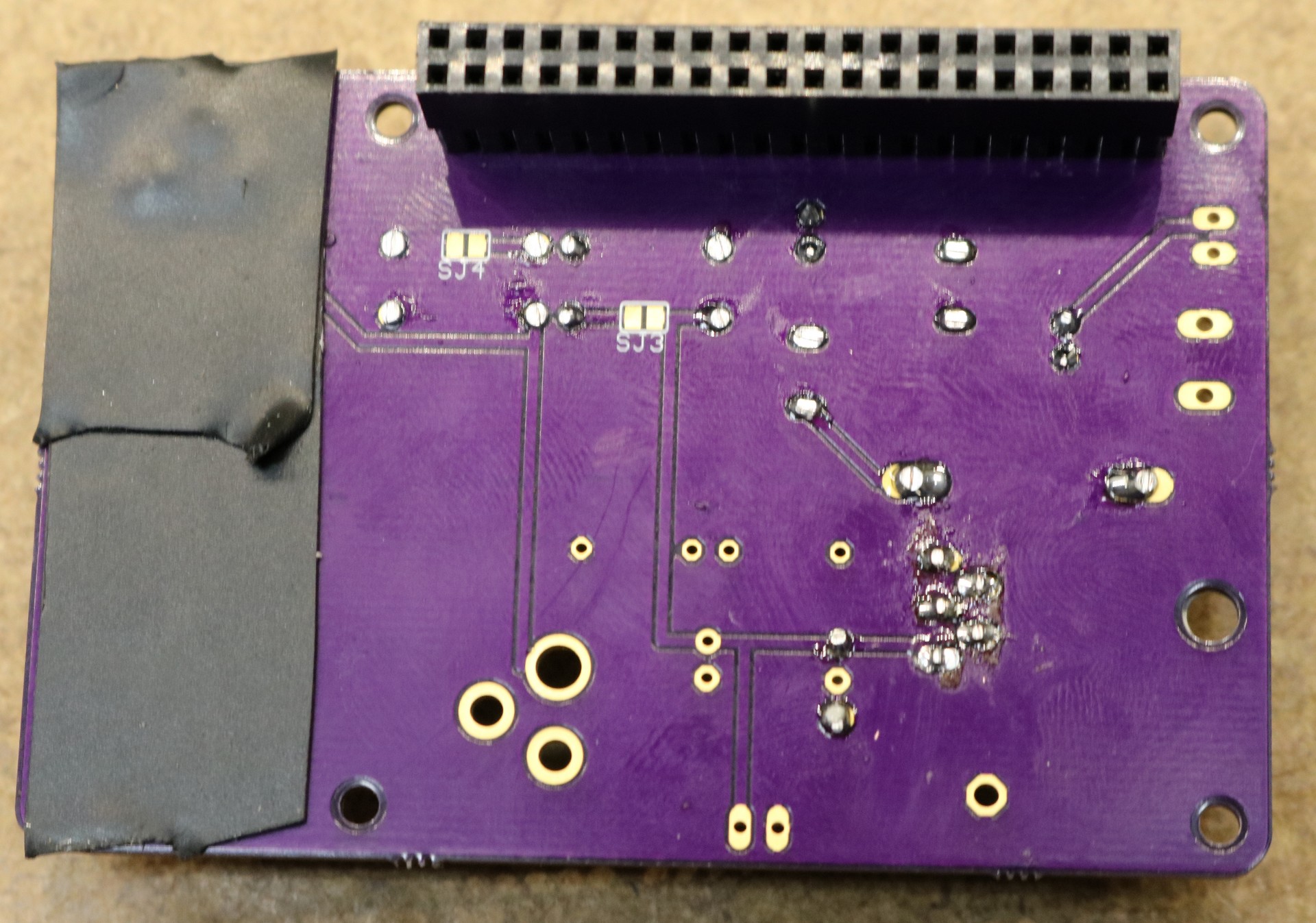
It might not be obvious from the image, but I used a stacking header so all of the GPIO pins are still usable. Only two of the Raspberry Pi pins are connected to — 5V and ground. I only soldered enough of the header to the PCB to make it mechanically sound.
When overlapping the Ethernet / USB ports, I added some thick black tape, just to make sure the bottom of the power jack doesn’t short against the ethernet / USB ports. The next revision, I’ll have to consider using a SMD power jack instead.
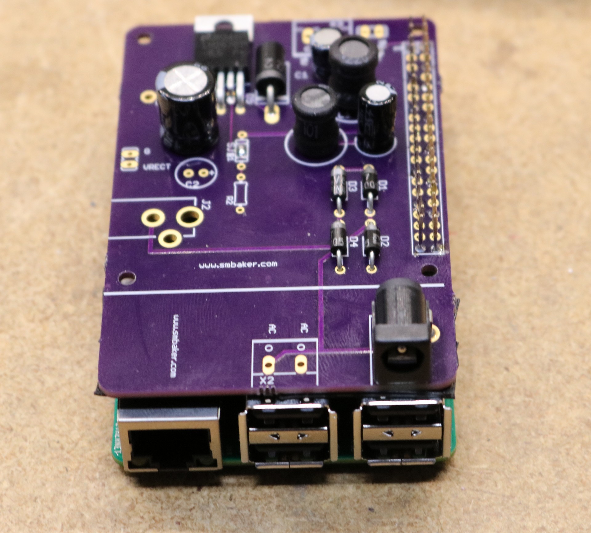
Here’s a picture of it mounted on top of a Raspberry Pi 2:
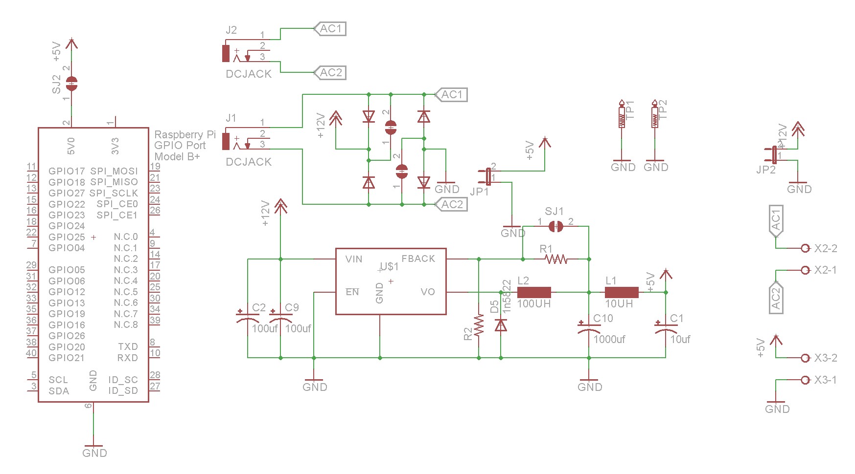
The schematic is right out of the data sheet for the LM2576 switchmode regulator:
Board ordering
As with many of my boards, I’ve shared it on OSH Park,


