In this video, I build a 3D Printed Desk lamp. The basic design came from Thingiverse, but I repurposed my LM2576 Constant-Current design to serve as a dimmer.
Motivation
It all started when I found an interesting lamp on thingiverse, https://www.thingiverse.com/thing:3328807, which used used 75mm air hose segments from another model, https://www.thingiverse.com/thing:3283786/, to make a flexible articulating desk lamp. What appealed to me about this project is the size of it, and the use of COB LED panels, which I’ve been wanting to experiment with. BigCliveDotCom had a nice video on the COB panels, https://www.youtube.com/watch?v=9F-WUcJlgko, that explained how to drive them and the appropriate voltages and currents.
I knew immediately that I wanted to drive these COB LEDs with my LM2576 Constant Current voltage regulator, originally described in another blog post, http://www.smbaker.com/lm2576-constant-voltage-constant-current-switching-power-supply.
A brief sidetrack to build a resistive load
I’ve been planning on building a resistive load for a while. I already have an active load, based on a design presented in an EEVBLOG post, that used an opamp and a mosfet to provide an adjustable DC load. However, I’ve often noted that I see occasional oscillations when using the active load on my power supply projects. Are these oscillations ripple in the power supply? or are they an artifact of the current-sense/op-amp/mosfet loop in the DC load? One way to figure this out would be to build a different kind of load, a completely passive resistor based load.
I started by buying a pile of 50 watt metal-encased resistors on eBay. Just search for “US Stock 4pcs 1 ohm 1 50W Watt Aluminum Housed Metal Case Wirewound Resistors” on eBay and you ought to stumble onto the same buyer I did, or similar. I purchased 1 ohm, 2 ohm, 4.7 ohm, and 10 ohm resistors.
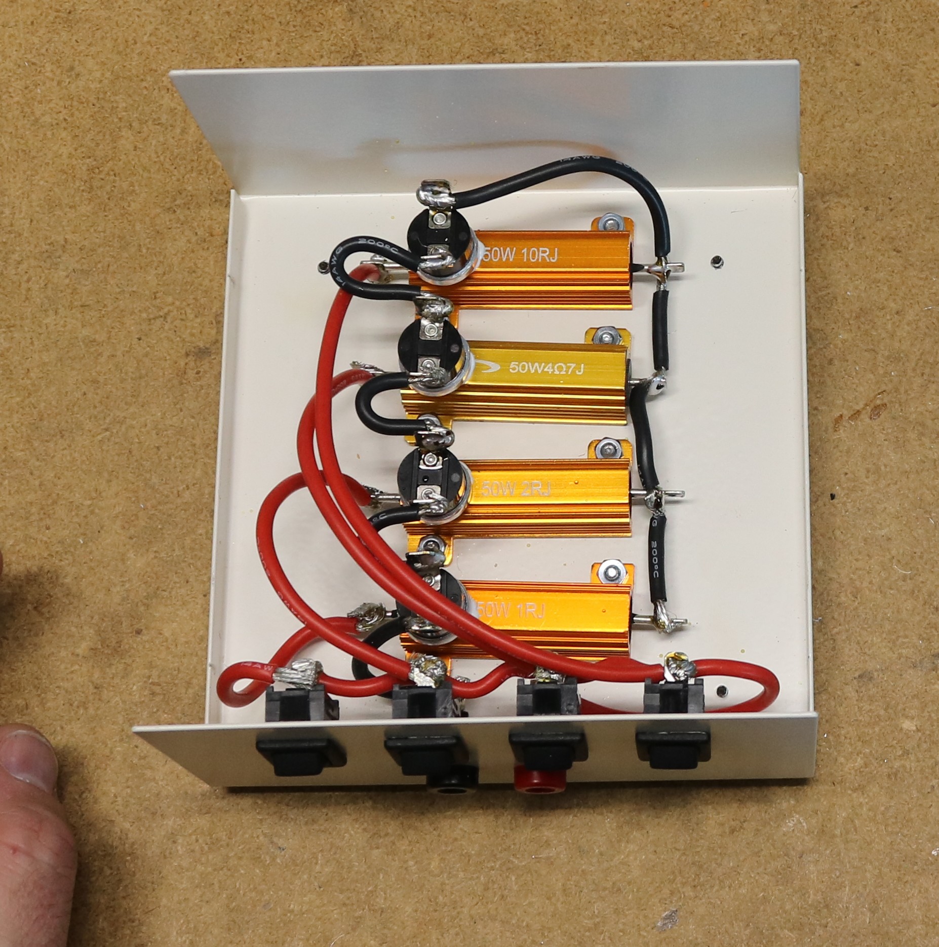
It was relatively easy to assemble these resistors into a Jameco instrument box,
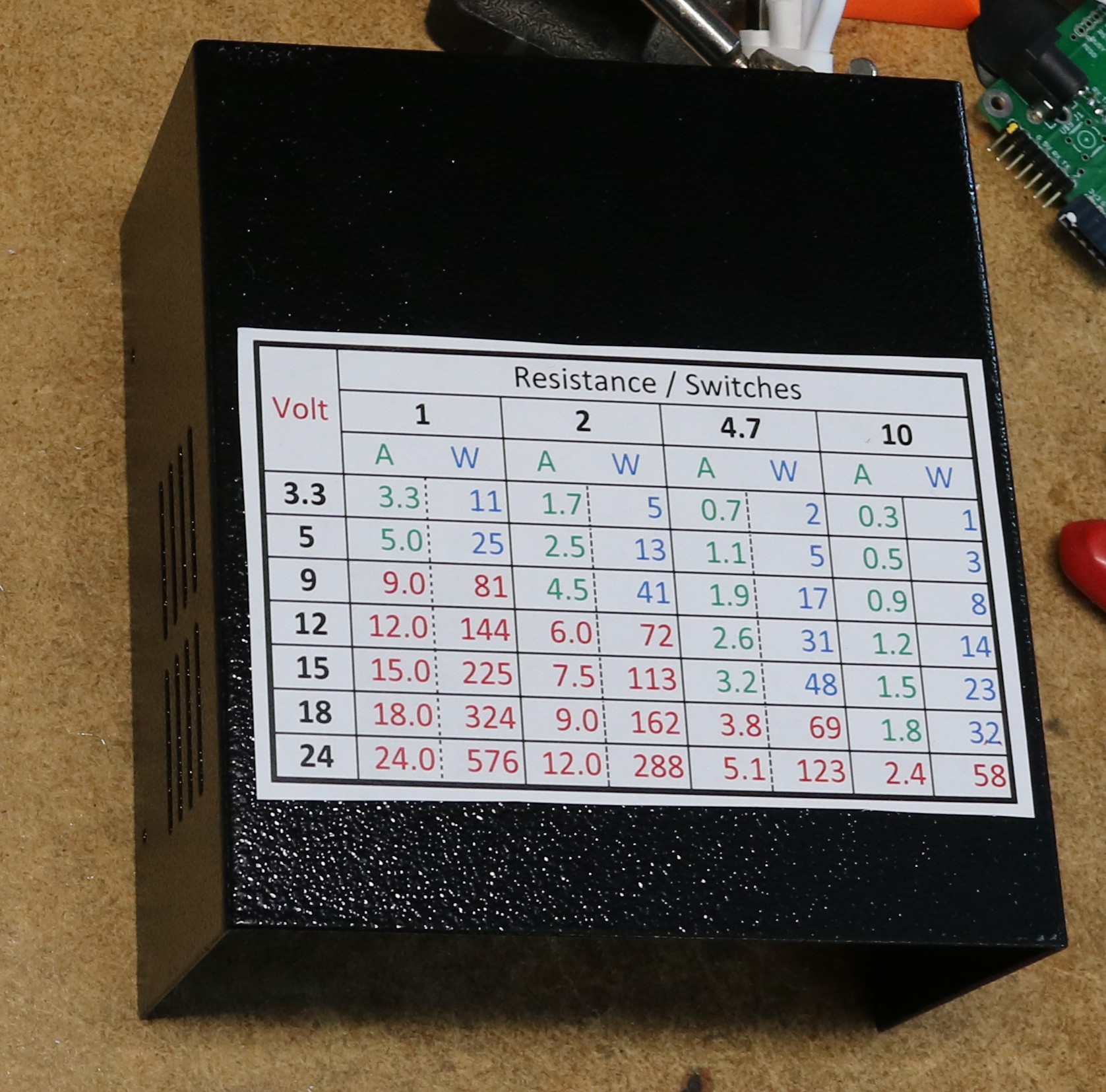
I wired the resistors in parallel using a set of rocker switches to allow them to be individually turned on and off, and I ran that out to a set of banana jacks. I placed a 150C thermal switch on each resistor as a temperature cutoff safety. One thermal cutoff mounted to the case would probably have sufficed, as I found the case does an excellent job of conducting heat from the resistors. On the top, I printed a chart of switches/resistors to amperage:
Now that the load was finished, I was ready to move on to building the power supply / dimmer.
Off to revise my LM2576 Constant Current design
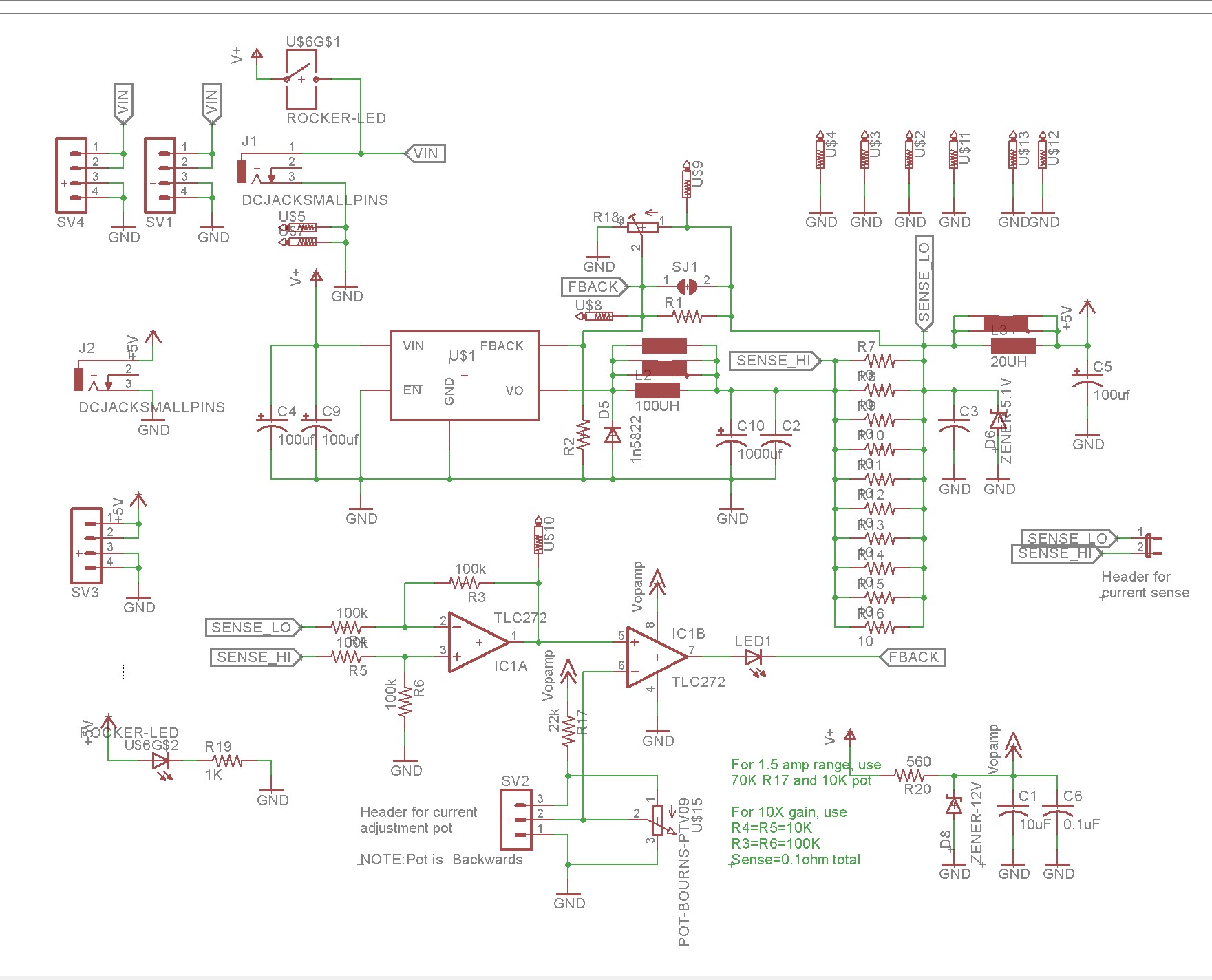
The basic circuit I had already designed and presented in a prior blog post. The only thing really left to do was to build a switch and a current set resistor into the circuit so they could all be mounted onto the same board. Here’s the schematic:
As I’ve already described this circuit in the prior blog post, I’m not going to go into detail. Suffice it to say that I made the following changes:
* Added some extra inductor footprints as the inductor I was using was undersized for working in the range of a couple amps.
* Added a rocker switch
* Added an onboard potentiometer for setting the current limit.
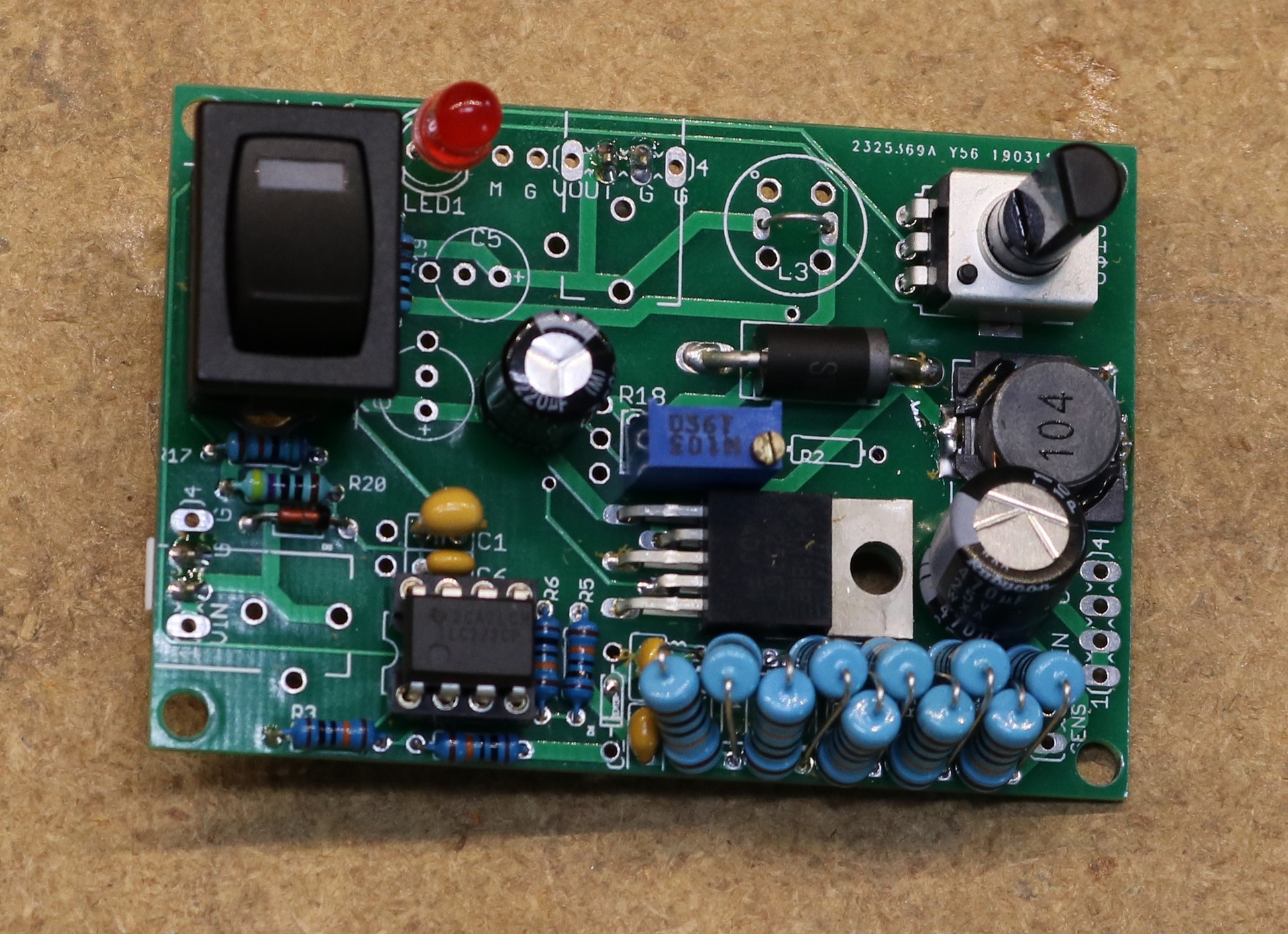
I designed the board to have the same dimensions and component (switch, pot, input and output connectors, etc) locations as the modules I used in my USB distribution system. Here’s the completed board:
Note that I’ve chosen resistors to give myself approximately a 1.4A range,under the assumption that I want to max out at two COB panels at 8 watts each. In reality you probably don’t want to run the COB panels that hot, but I went for having a little bit of extra range. This meant using a 10K pot together with a 75K resistor for R17. I would have gone for 70K to give myself a little more range, but 75K was as close as I had.
That sure got hot…
Testing the board out with a 1 ohm sense resistor (ten 10 ohm resistors in parallel) got hot. About 250 degrees hot, with almost two watts of wasted power. I decided now was the time to see if I could safely use a smaller sense resistor.
This was easy enough, I made a second board, instead using ten 1 ohm resistors, for an overall sense resistance of 0.1 ohm. Then I upped the gain on the op-amp from 1X to 10X. The circuit behaved exactly was before, with the exception of slightly more ripple while the constant current mode is engaged. 0.440 volts peak-to-peak instead of 0.380 volts peak-to-peak. That’s a tradeoff I can accept, to reduce energy waste and heat generation. The schematic above documents the component substitution necessary to make the change.
Let’s talk about COB panels
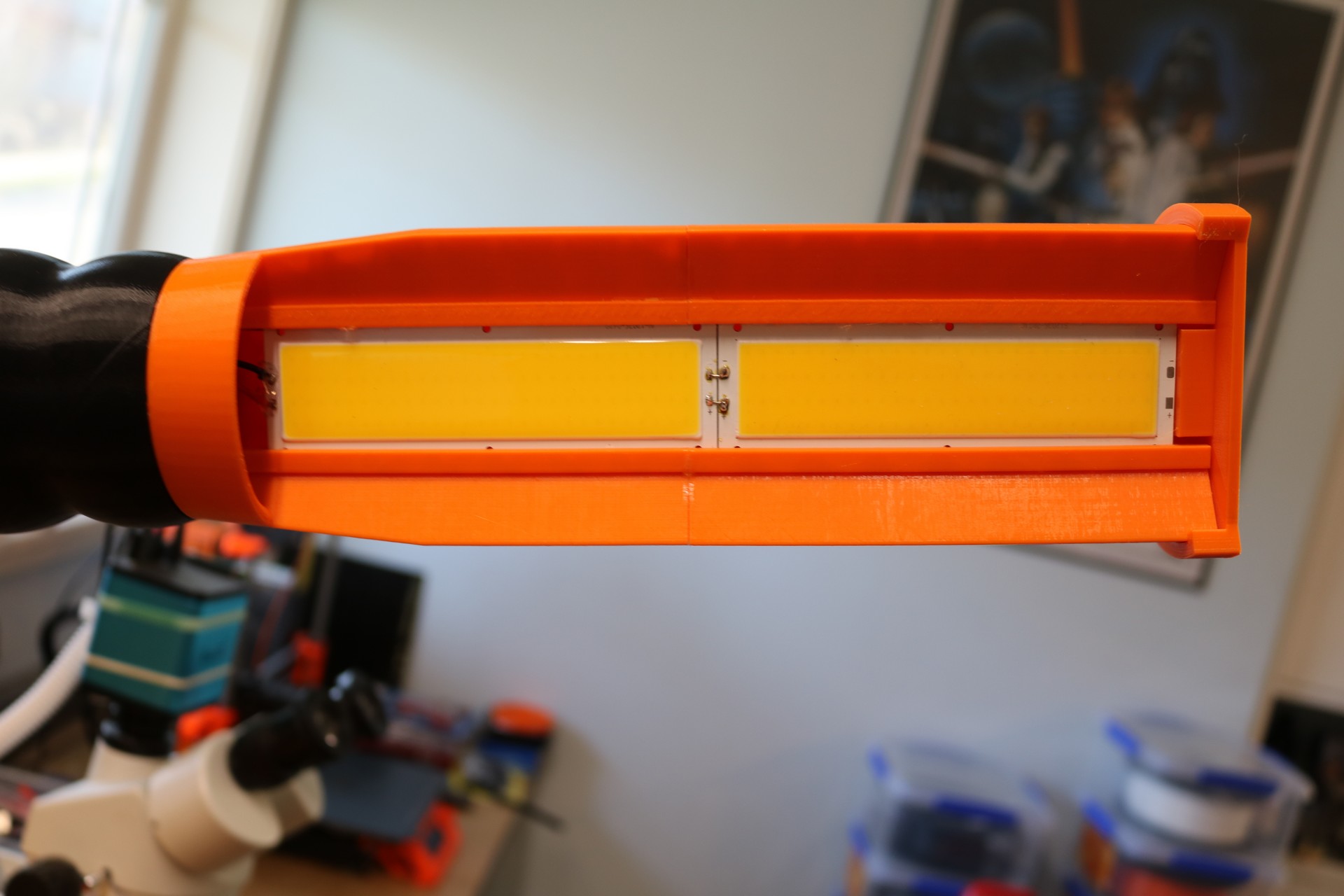
The COB panels used in the lamp are the most interesting part of this project. Here’s a picture of the lamp head:
BigCliveDotCom has an excellent video on these panels, so I’m not going to try to go through all of that here. I’ll just list a few of the high points:
* There is no current limiting in the panel, you need to limit the current (or the voltage) yourself.
* The panels are really cheap, under 2 bucks each.
* They’re typically described on eBay as “10W 12V COB LED Panel Rectangle Strip Car COB Chip Light Panel Lamp 1000LM” or such.
* Although they have a nice think aluminum panel behind them, they will throw off a lot of heat. I recommend derating them a bit and running them less than 10 watts. I figure around 8 watts to be a safe derated limit though in practice I tend to run them less than that.
* I printed my lamp in PETG for some degree of temperature resistance. So far I haven’t melted the lamp yet. So far.
Build a lamp!
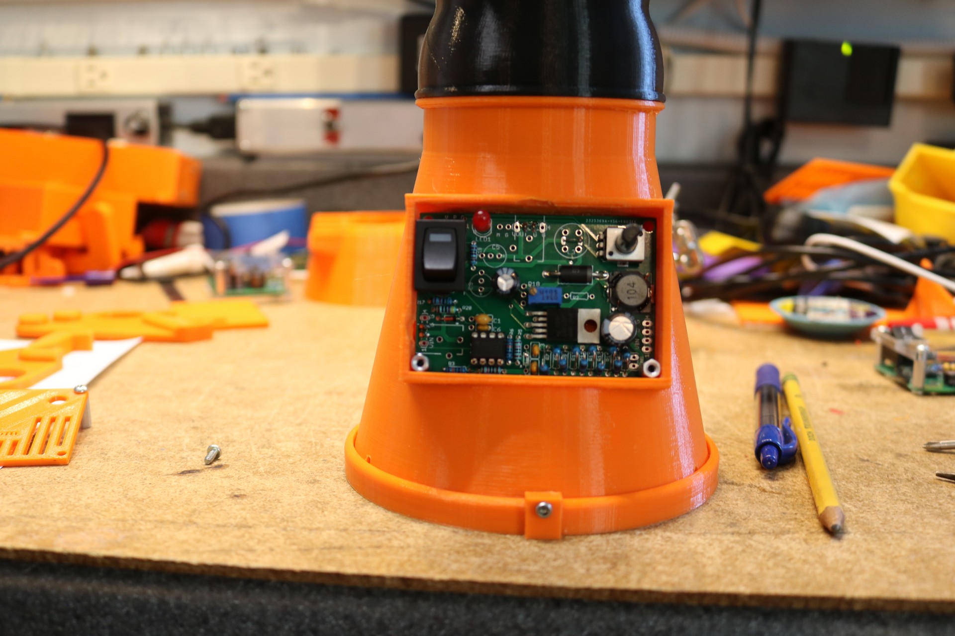
My video has a lot more detail on printing the lamp, so if you want some 3D printing information and assembly information then I suggest you watch the video. Regardless, here’s a picture I took of the electronics mounted in the lamp base:
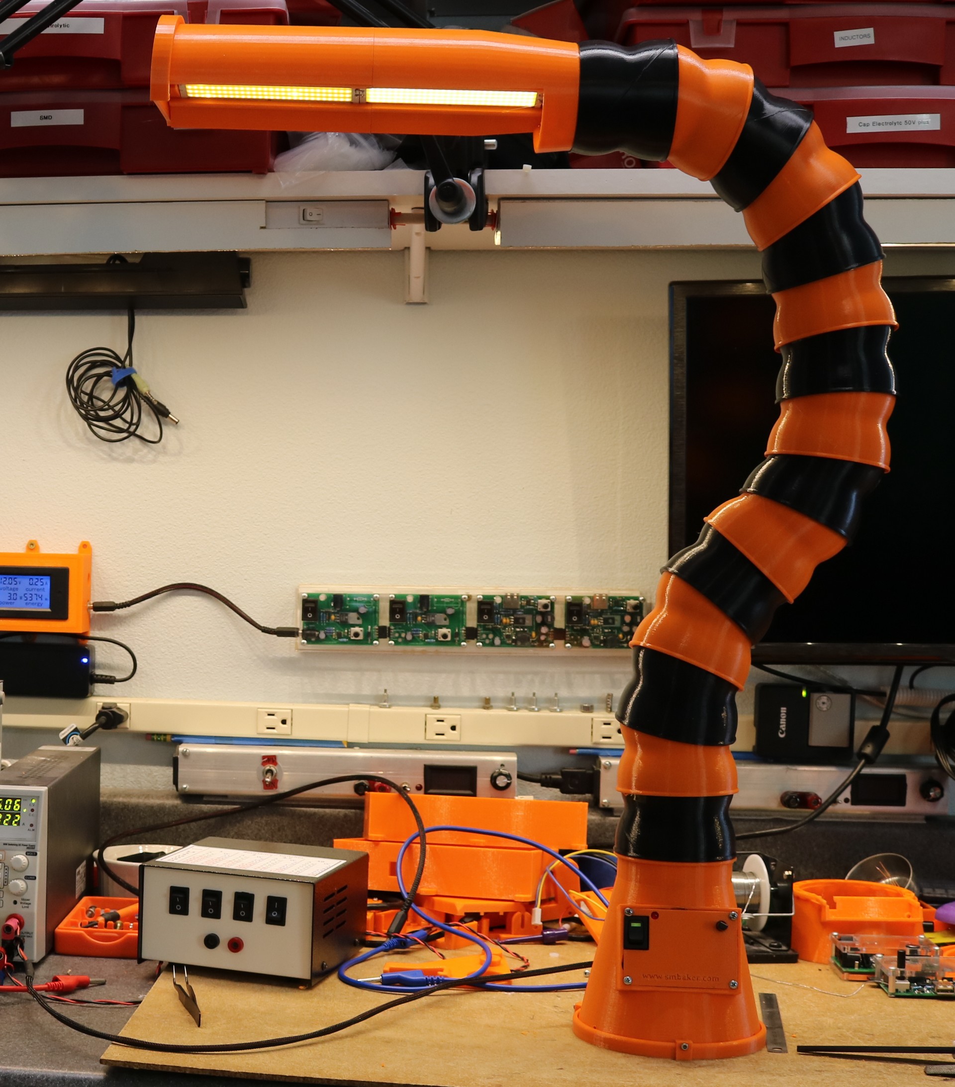
Here’s a picture or two of the completed lamp:
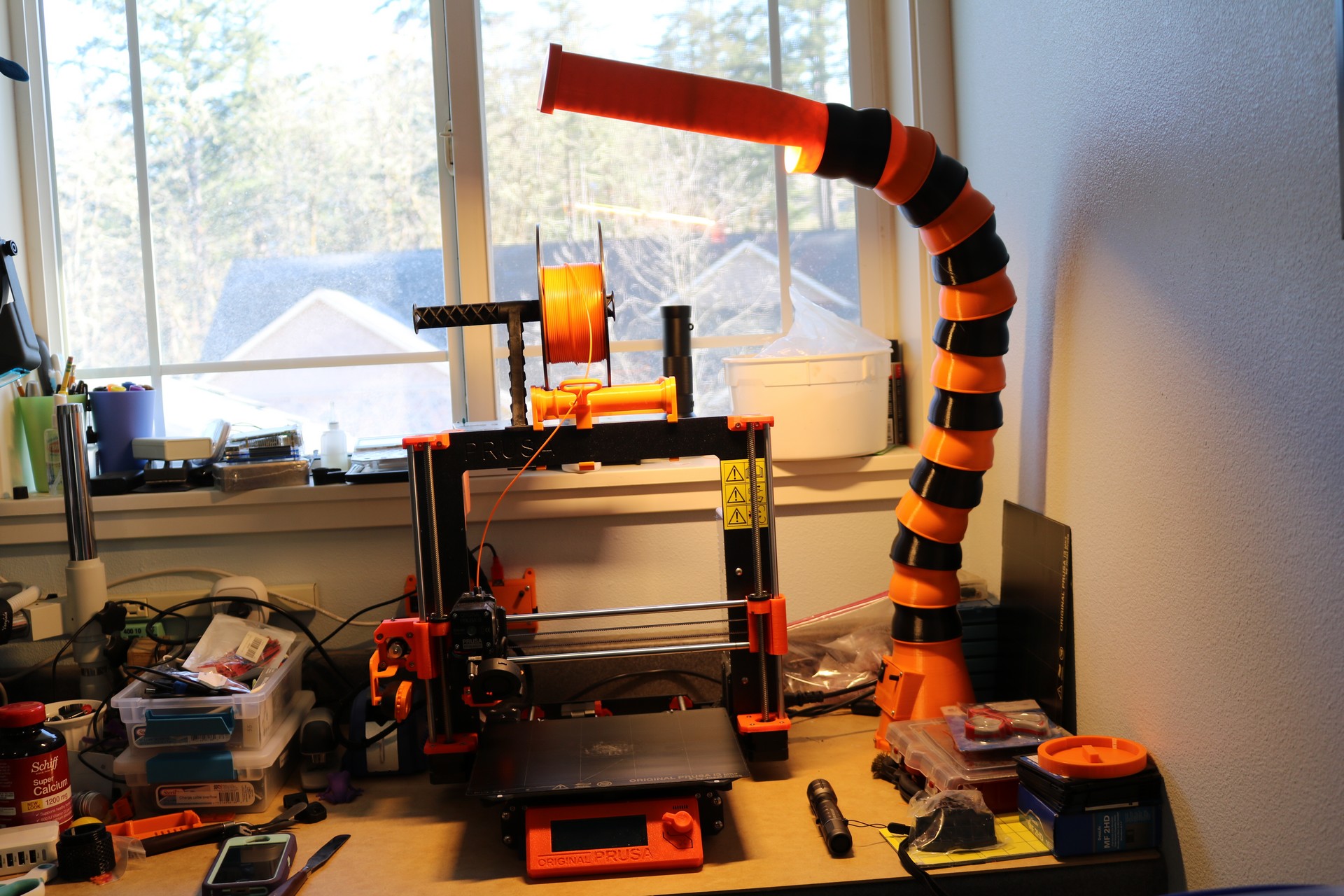
In the picture above it might look like the panels are different colors, but I think that’s more due to the effect of different brightnesses (either that or I bought a warm-white and a bright-white without noticing… but I don’t think so). I had the dimmer turned way down in that image, and since one panel is connected after the other, and they’re wired in parallel, I think the first panel got more juice than the second. The lamp is really large, you can see how large when comparing it to my Prusa 3D Printer:
Resources:
My remix of the lamp is at https://www.thingiverse.com/thing:3498571, and includes changes to the fixture so it prints in two pieces, changes to the base to incorporate the constant-current power supply, and changes to the baseplate so it can be attached with machine screws.
