In this video, I make a Nixie Tube Filament Meter / Progress Meter:
History
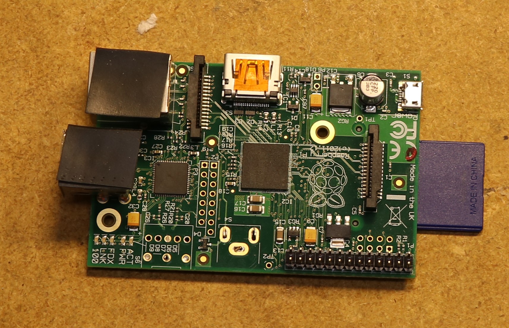
I’ve made a lot of Nixie Tube projects over the years. This particular one started out as an Ethernet-based thermometer/hygrometer display. It used a Raspberry Pi Model B (the original one!) to interface to some ethernet-based sensors that I had. I built this back around 2013, and a few years ago it failed and got thrown on the shelf awaiting repair. I pulled it out last weekend to see if I could repair it. The problem was simple enough — I had used double-faced tape to insulate between the pi’s USB connector and the nixie tube driver ICs. Over the years the pins on the IC wore through the double-faced and shorted it out. I removed the double-faced tape and replaced it with some more durable rubber insulating tape. A simple enough fix, and the board was working again.
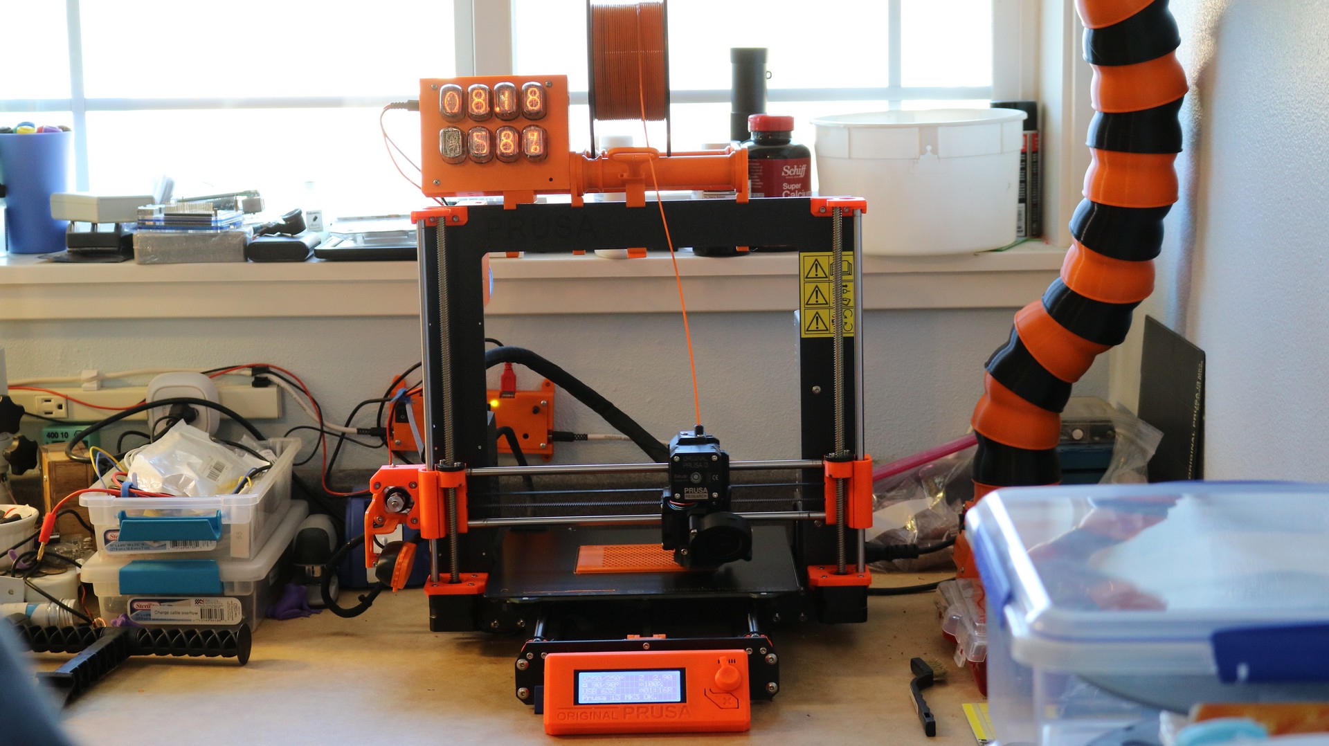
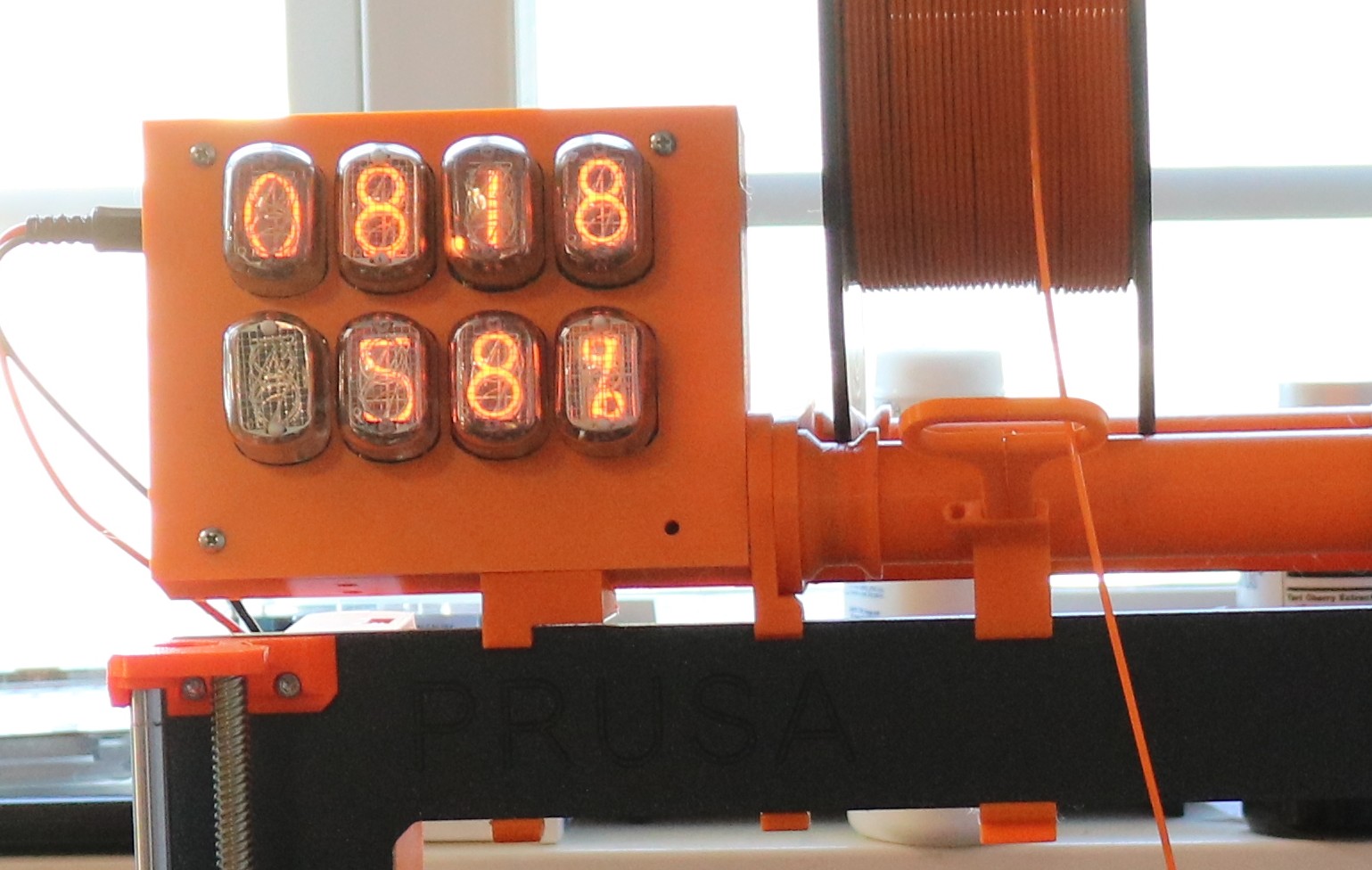
Turning it into a Filament Meter for my 3D Printer
First, I decided to upgrade from the Raspberry Pi Model B to a more recent Raspberry Pi Zero W that I had on hand. Wired Ethernet is so ~ 2013 after all, and wireless would be a lot more convenient. Next, I designed a 3D printed case for it, as my old laser-cut-acrylic-and-glue case also looked very dated. Finally, I replaced the software with a new program designed to poll the data from my octoprint server. In less than an afternoon, I had turned the old temperature/humidity display into something useful.
Design
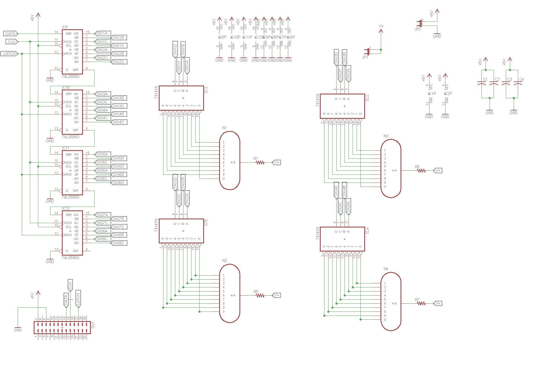
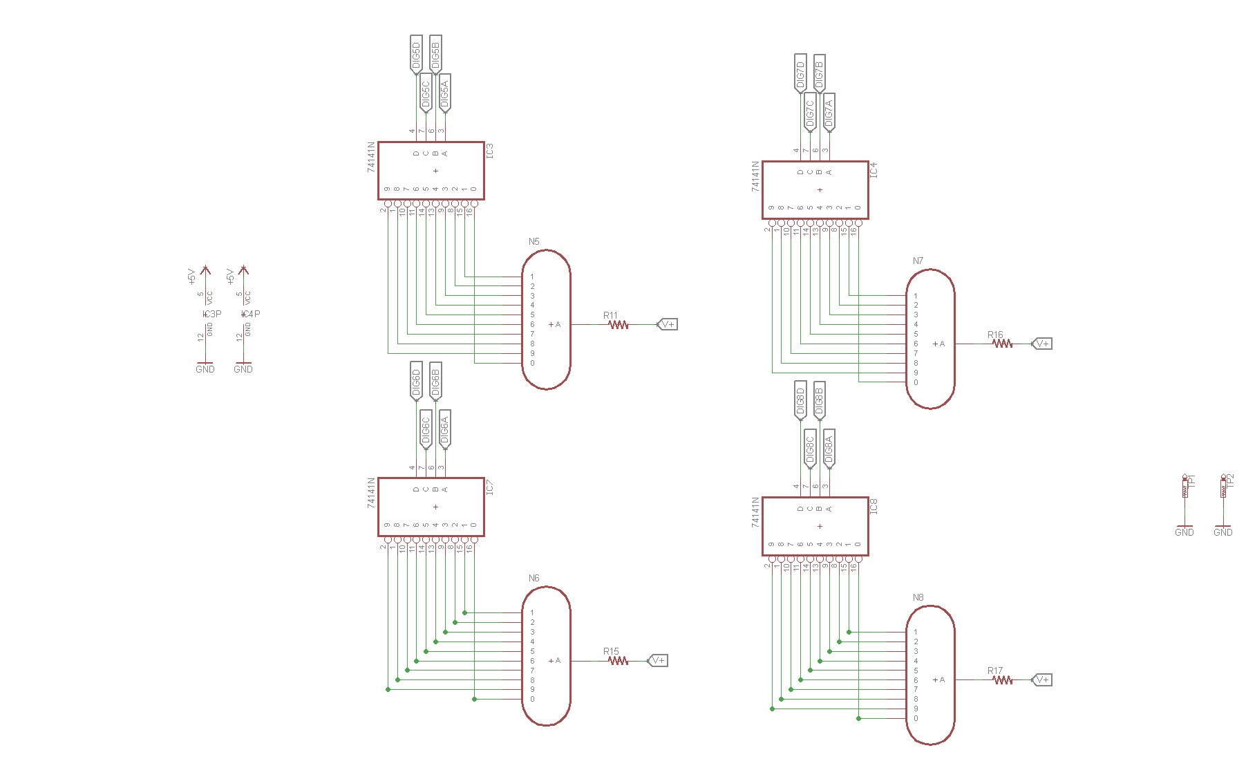
Technically, this is an old project that was repurposed, but I don’t recall if I ever did a blog post on it. Here is the schematic:
Each Nixie Tube has one 74141 (aka K155D) driver chip associated with it. This is where one often has some design alternatives — a lot of Nixie Tube clocks will use multiplexing, alternatively displaying digits in order to reduce part count and GPIO count. Personally, I like to use one driver per tube and avoid the multiplexing, so I can “set it and forget it” with the displays rather than having a loop to continuously refresh them. Eight tubes with four BCD pins per driver is 32 bits of IO necessary to drive the tubes. In order to do that from a Raspberry Pi, I opted to use some 74HCT595 shift registers. The shift registers allow you to send serial data from the microcontroller, using only three pins of GPIO, to provide 32 bits out of output. The three pins are: data, clock, and latch. You put a bit on the data line, then you strobe the clock to load that bit. Once all 32 bits are loaded into the shift registers, you strobe the latch pin to make them live. Using shift registers like this is a pretty common technique.
Each tube has a current limiting resistor on the anode. There’s a high-voltage power supply on a daughterboard that supplies the necessary high voltage to drive the anodes.
Implementation
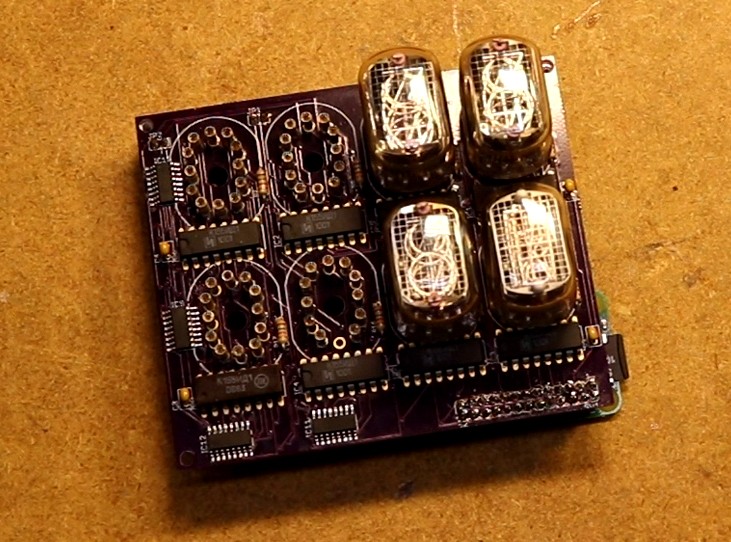
I didn’t take a whole lot of pictures of the pcboard — the video might do it more justice than these pictures, but here is a still shot:
These are old-style nixie socket pins that I was using six years ago, I’ve since switched to newer flush mouser pins. If I do a respin of the board, I’ll probably switch to the newer style. I also opted for putting the ICs on the same side of the board as the tubes, that’s something I have changed in my more recent designs (flush socket pins = no room for ICs on the top of the board, so flip em). The driver chips are through-hole because these are vintage ICs and that’s all that is available. The shift registers are SMD devices, because I needed them tiny to fit them on the board. There’s a raspberry pi connector on the lower right side.
There is no logic for driving the decimal points. I put pads on the back, so it’s easy to ground the decimal point pins on the 3rd tube in each row. This gives you a fixed decimal point at build time, which is fine if you know where you want the decimal point to be. In this case it worked out alright.
Software
The software is available in my github repo at https://github.com/sbelectronics/filadometer. It makes use of another program I wrote, a prometheus endpoint plugin for Octoprint. The prometheus endpoint makes all of the necessary statistics available in one convenient HTTP GET request. The Nixie Filadometer code merely polls that endpoint periodically and updates the displays.
I could have eliminated the separate raspberry pi and used the OctoPi’s GPIO, but it seemed safer given the high voltages involved to make this device completely independent of my 3D printer.
To-do list
I’m considering a respin of the pcboard, and if I do so, will probably make the following changes:
1) Software-controllable decimal points. This probably means a fifth shift register and some transistors. Space is tight, so maybe I try to put it on the opposite side of the board from the current shift registers. Or maybe I have to make the board bigger.
2) Software-controllable HC power supply enable. The TL494 in the power supply can easily be switched on or off with an enable pin. It would be really nice to disable the HV PSU while not in use.
3) Use newer nixie sockets. I really like the flush-mounted mouser pins. This probably means flipping the ICs to opposite side of the board as the tubes.
4) Integrate the power supply into the board rather than having a separate daughterboard. This would necessarily make the board bigger to fit the additional components, but would allow for simpler implementation.
5) Buttons. I wouldn’t mind a button that allowed displaying different data on the tubes. For example, time remaining or hot end temeprature would be nice. Again, probably means making the board bigger.
I have more cool displays than I know what to do with. I never thought of this as a project idea. I may have to copy the idea of this project. Thanks for sharing!