In this post, I turn the Multibus computer into a Nixie Tube Clock
Background
I like Nixie Tubes, and I’ve made a fair number of projects — my Nixie Tube Calculator, a Nixie Tube Clock RC2014, even a PC Clone with a built-in Nixie Tube display. I felt like it was finally time for another IN-12 Nixie Tube project, so I added a Multibus Nixie Tube board. The board features up to eight IN-12 Nixie Tube displays, a built-in 170 volt DC power supply, and a couple multimodule slots (you can never have too many mutlimodule slots)
What is a Nixie Tube?
Nixie tubes are electronic devices used for displaying numbers or symbols. They consist of a sealed, transparent glass “vacuum tube” filled with a low-pressure gas such as neon and contain multiple cathodes shaped like numbers or symbols. Each cathode is individually shaped to form a specific number, usually from 0 to 9, and is stacked in layers inside the tube. Some tubes, such as the IN-15 have symbols. In this video, I use the number tubes, the IN-12.
When a particular cathode is energized (by applying a voltage), it glows with an orange-red light due to the ionization of the gas around it. Only one cathode is illuminated at a time, making the corresponding numeral visible. Nixie tubes were widely used in the 1960s, maybe a bit in the 70s and perhaps in eastern Europe even into the early 80s. They make a fun nostalgic display for a vintage computer project.
Design
I chose to use IN-12 Nixie Tubes. They’re my favorite, because the facilitate an easy plug-in design, together with Harwin H3161-01 socket pins which you can get from Mouser. The Tubes themselves you’ll usually have to source from eastern Europe. I believe mine came from Ukraine.
The design of the board is relatively straightforward. Rather than choose a multiplexed design that requires constant update from the CPU, I went with a driver-and-latch design where each tube has a dedicated nixie tube driver using a K155D driver chip together with a 74HCT273 latch. The 74HCT273 latches the 4 BCD bits for the driver as well as a decimal point bit. The K155D (aka 74141) drives the cathodes in the Nixie Tubes.
I have embraced multimodules for expansion capabilities. Multimodules are small modules, slightly smaller than a postcard, that plug into a host multibus board. I designed the Nixie Tube board with a couple multimodule sockets that I can use to mount a GPS or RTC multimodule for timekeeping, as well as a speech synthesizer multimodule for speaking the time.
The Nixie Tube Multibus Board
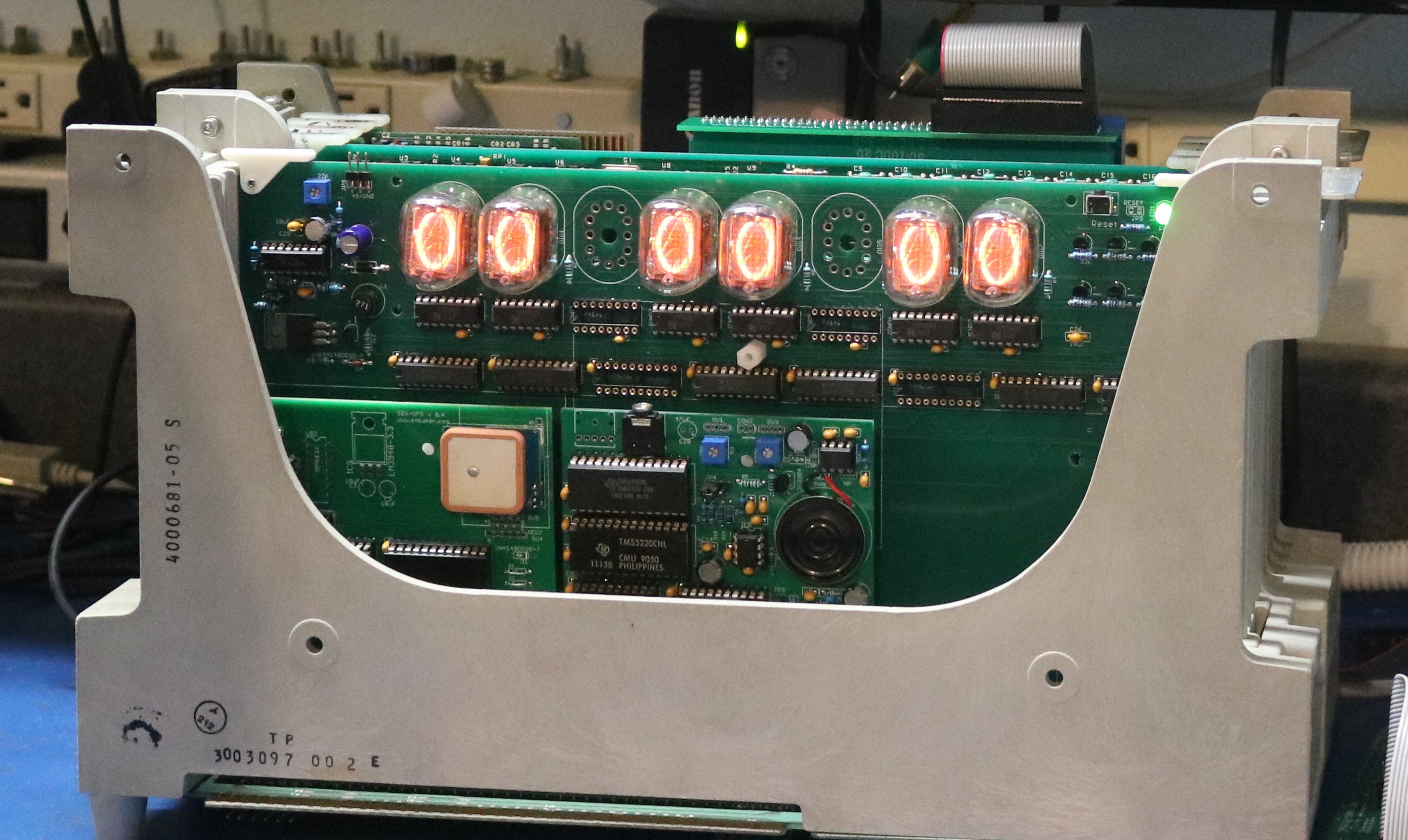
The full schematics you can find in github at the links section at the bottom of this page. Let’s take a look at the board:
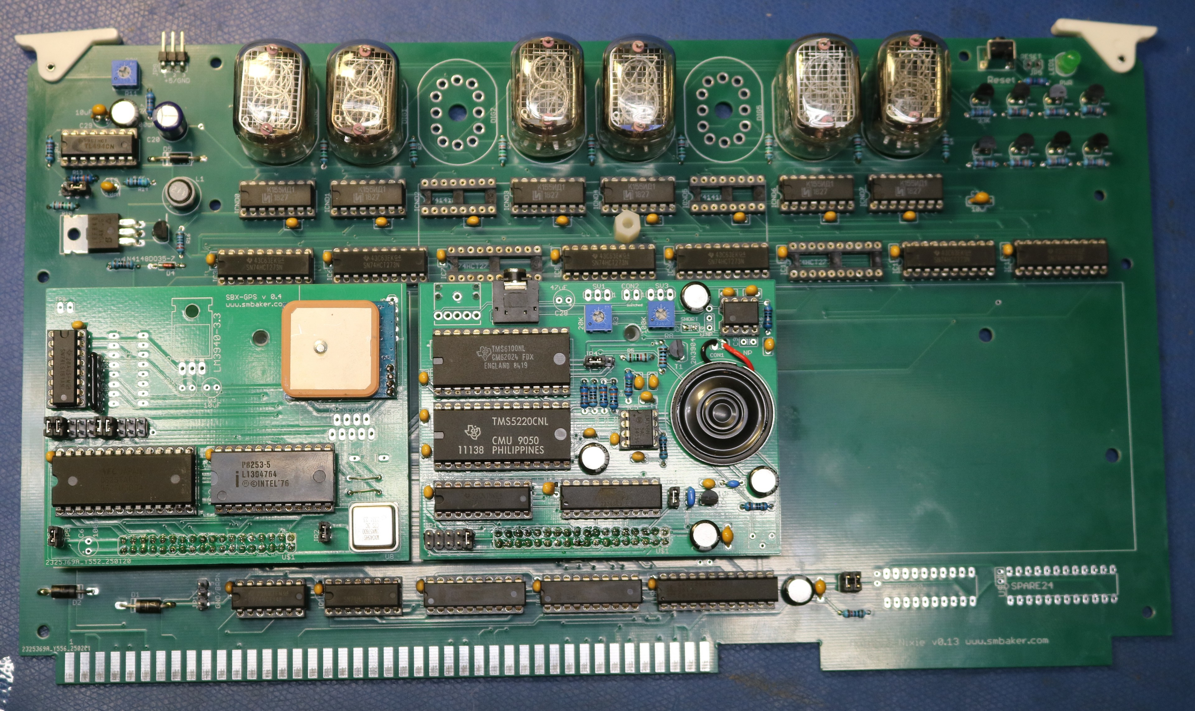
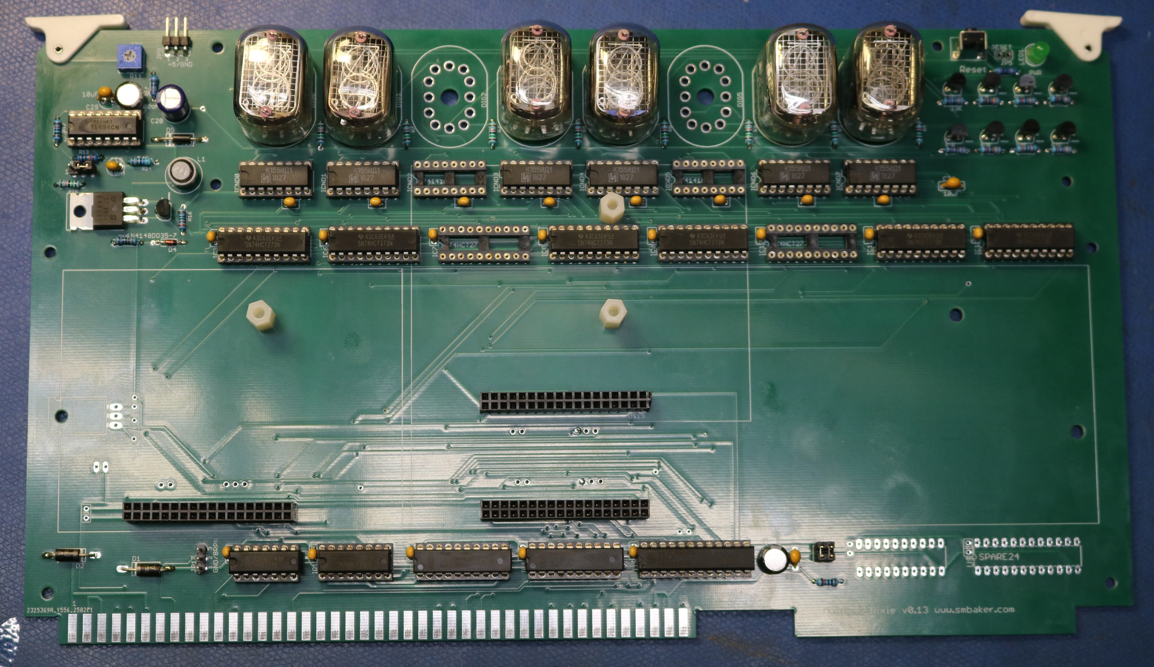
Above is a picture of the board with a GPS multimodule and a TMS-5220 speech synthsizer multimodule installed. Below is a picture with the two multimodules removed:
Multimodules
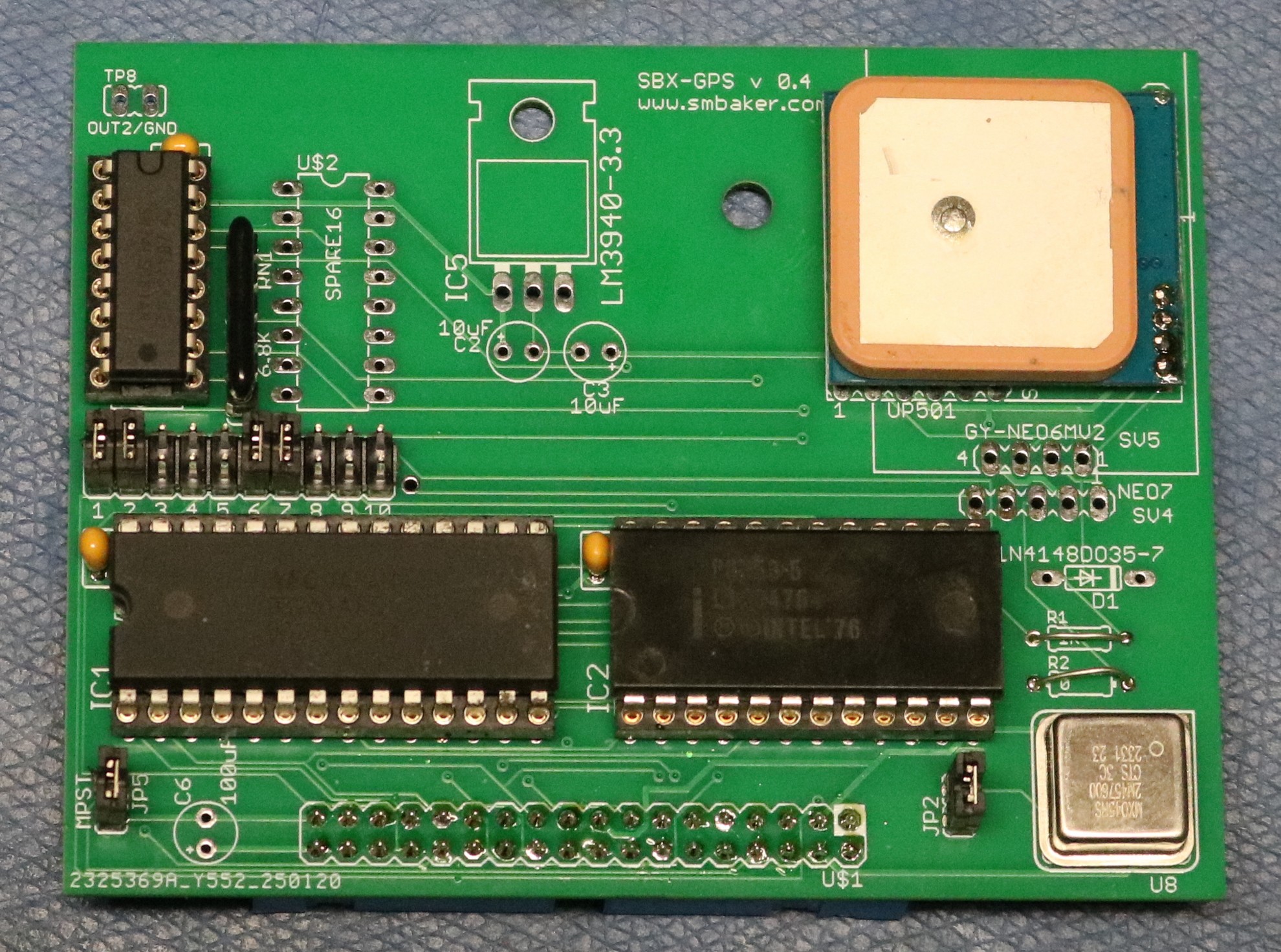
Here are some of the multimodules that I used in the video with the clock board. First up we have the GPS multimodule. You can use it to set the clock automatically using GPS as a timekeeping source:
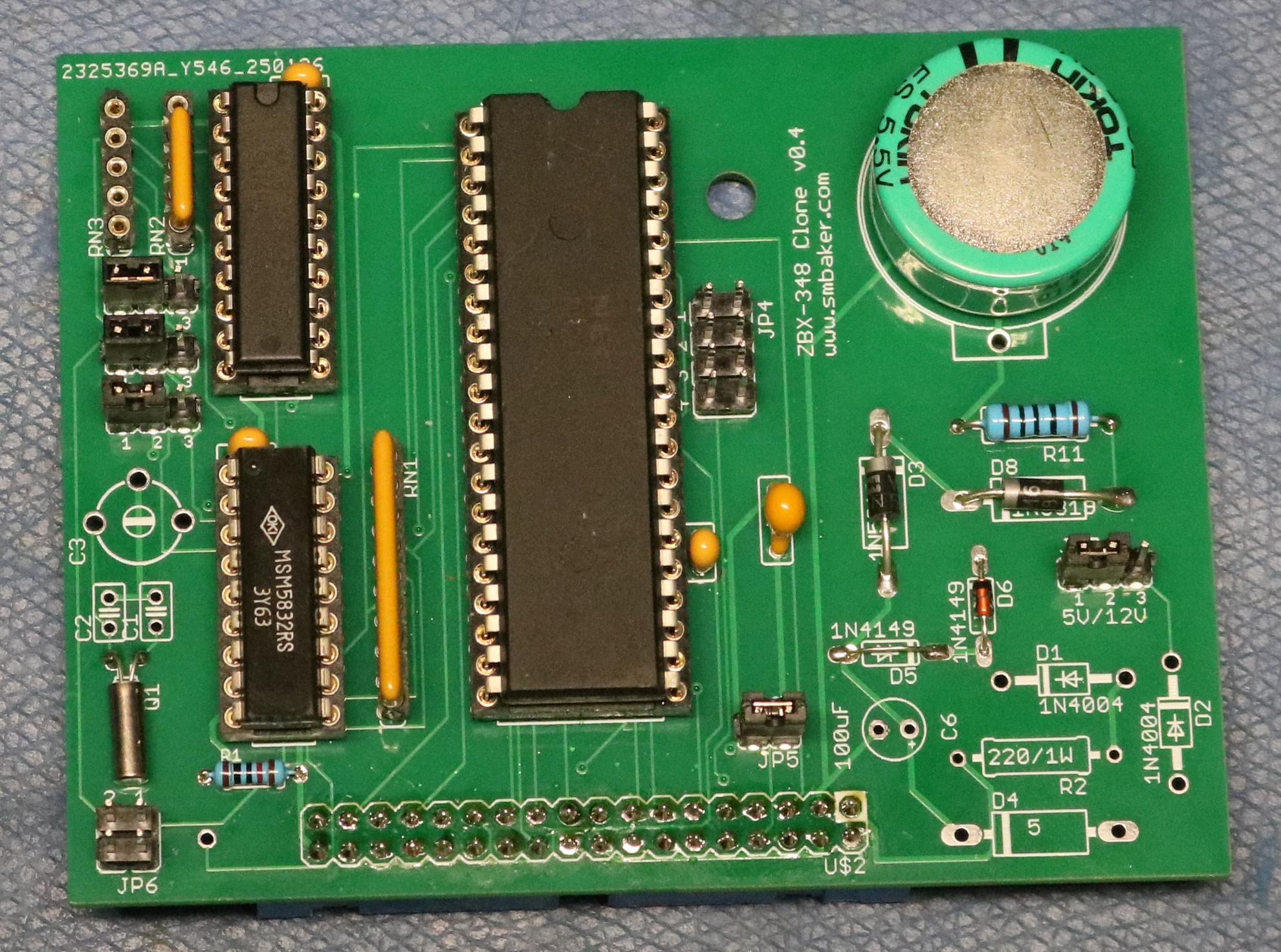
Next is the RTC multimodule. Use this one if you want something a little more period-accurate than a GPS. It uses an MSM5832 realtime clock and either a supercap or a lithium cell as battery backup. It doesn’t set itself — if it loses power, you’ll need to set it.
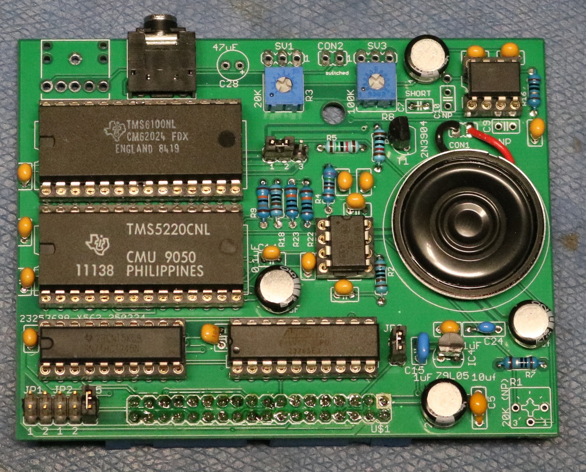
Next we have a speech synthesizer. This is my TMS5220 speech synthesizer, detailed in a prior blog post:
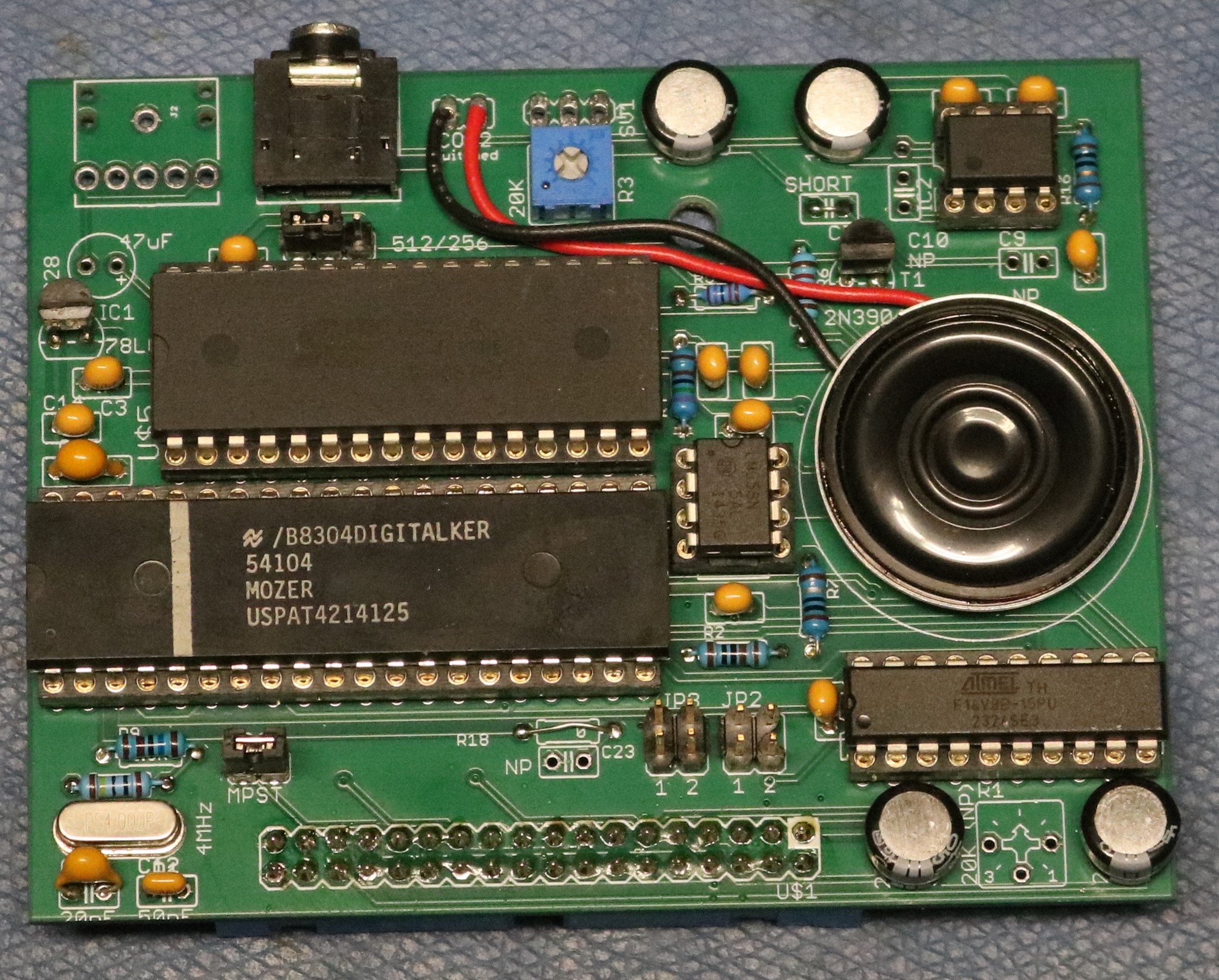
Finally, here is a speech synthesis module using the National Semiconductor digitalker chip:
In the blog video, I mixed and matched a bit showing off both timekeeping modules as well as both speech synthesis multimodules.
Resources
- You can find the schematics, gerbers, PLD files, and code in my multibus repository.
Dr. Baker,
I am new to your 80/24A project. I looked around many ISIS-II related websites but cannot find correct source code to compile for 32K ROM. Could you point me to a link ? Thank you in advance.