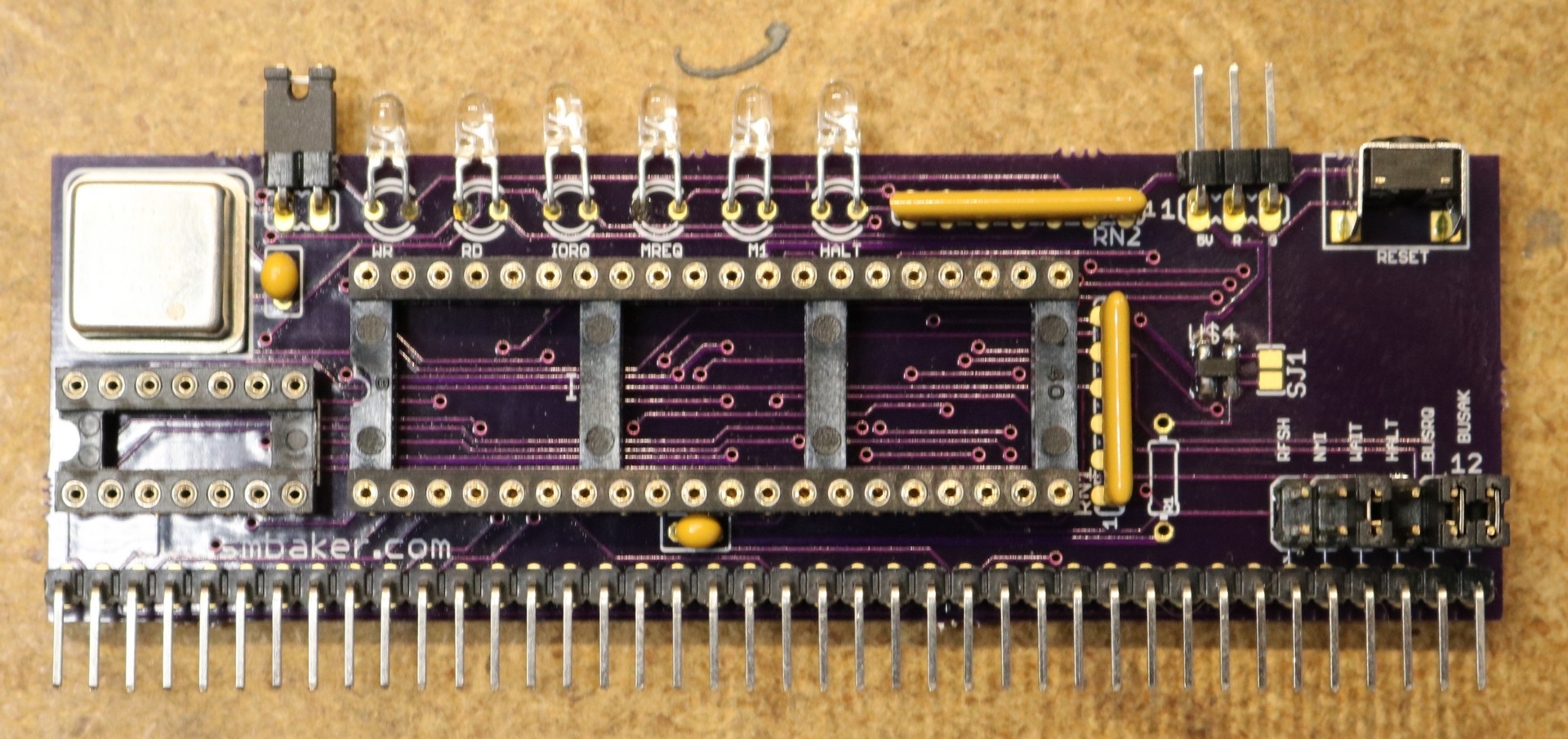
I set out to build a fancier CPU board:
Design
I wanted the CPU board to have the following features:
- on-board oscillator, so that a separate clock board is not necessary
- power-on reset circuit
- reset header for external reset switch
- status LEDs for common signals such as RD, WR, MREQ, IOREQ, M1, and HALT
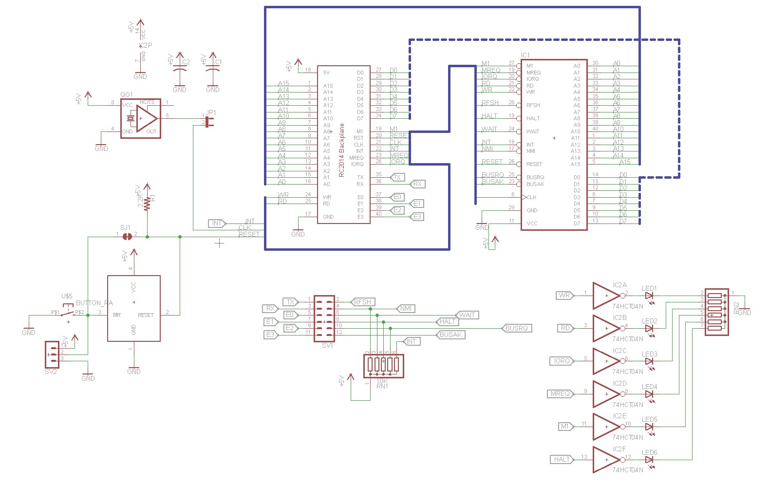
Below is the design that I came up with:
The oscillator footprint is entirely optional and can be selected by jumper JP1. Regardless of the setting of this jumper, the Z80 is connected to the RC2014 BUS’s CLK pin. So that mean that if you leave JP1 unjumpered, you can use an external clock board. If you install the osciallator and jumper JP1 then you had better not have installed an external clock board, as you would end up with two clocks operating simultaneously.
Status LEDs are operated by a 74HCT04 hex inverter. The inputs of the hex inverter are connected to WR, RD, IORQ, MREQ, M1, and HALT respectively. A SIP resistor handles current limiting for the LEDs.
I used a MAX811 for the power-on reset circuit. See my blog post on Z80 Reset Circuits for more information.
That’s about it, this is a pretty simple board.
Implementation:
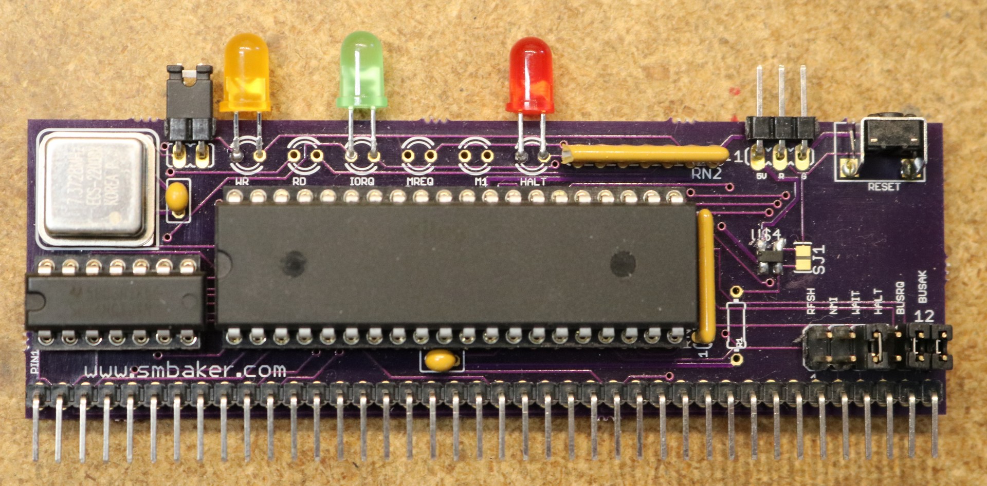
I build two of these:
The first one had all six LEDs, but that turned out to be overwhelming. As long as the CPU is running at typical megahertz speeds, the M1, MREQ, and RD lights appear to be lit all the time. This is because unless it is halted, the CPU is pretty much always fetching instructions. I used high-efficiency blue LEDs, so it was also really bright and hard on the eyes to look at.
For my second prototype, I installed only the LEDs that show useful information — Halt, IORQ, and WR. The Halt LED will light up when the CPU is halted. For RomWBW that’s not too interesting, but for Fuzix it’s cool as the CPU Halts everytime Fuzix is idle. The WR LED lights up for both memory and IO writes. The IORQ light lights up for IO reads and writes. This is useful, when you access the disk or terminal or do something else IO-heavy, you’ll see lots of activity on IORQ. Programs that are writing to a lot of memory will have the WR light lit a lot.
If I was to do this over again, I’d probably use a NAND gate, so that I could break out IO-Write, IO-Read, and Memory-Write.
PC-Boards
As usual, I’ve made the board available on OSH Park for anyone who is interested:


I ordered and built your Enhanced Z80 board design. It is a BIG improvement. The only suggest I have is to replace the MAX811 with something like the DS1233-5 (in a TO-92). The MAX811 SOT is hard to solder. At Digi-Key, the MAX811 costs $3 in small qty. The DS1233 costs $1.56. It would make the board less expensive and easier to build.
Do you happen to know the part number for the reset switch you used?
sean
Also will this support a 20MHz Z80, i have a few 10MHz ones laying around but was going to get a 20MHz if it would support it.
sean